Statement of Principle of Continuity:
When an ideal liquid (i.e. incompressible and non-viscous liquid ) flows in streamlined motion through a tube of non-uniform cross-section, then the product of the velocity of flow and area of cross-section is always constant at every point in the tube.
Mathematical Analysis (Proof)
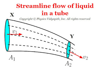
Let us consider, an ideal liquid (i.e. incompressible and non-viscous liquid ) flow in streamline motion through a tube $XY$ of the non-uniform cross-section.
Now Consider:
The Area of cross-section $X = A_{1}$
The Area of cross-section $Y = A_{2}$
The velocity per second (i.e. equal to distance) of fluid at cross-section $X = v_{1}$
The velocity per second (i.e. equal to distance) of fluid at cross-section $Y = v_{2}$
The volume of liquid entering at the cross-section $X$ in $1$ second is = $A_{1}v_{1}$
The mass of liquid entering at the cross-section $X$ in $1$ second is = $ \rho A_{1}v_{1}$
Similarly, the mass of the liquid coming out from the cross-section $Y$ in $1$ second is = $ \rho A_{2}v_{2}$
But the liquid which enters at cross-section $X$ must leave cross-section $Y$. Hence the masses are equal at both cross-section area, that is,
$\rho A_{1}v_{1} = \rho A_{2}v_{2} $
$ A_{1}v_{1} = A_{2}v_{2} $
$A v = constant$
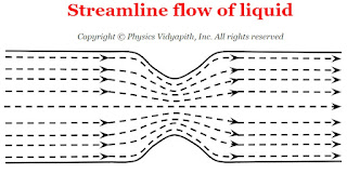
Thus, the above equation shows that at every place in the tube, the product of the area of the cross-section of the tube and the velocity of the flow of the liquid is always the same. Therefore, the velocity of the liquid is smaller in the wider parts of the tube and larger in the narrow parts.
Combined Focal Length and Power of two thin lenses in contact
Derivation of the combined focal length and power of two thin lenses in contact:
Case (1): When both are convex lens-
a.) The combined focal length of two thin convex lenses in contact:
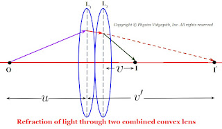
Let us consider that two convex lenses $L_{1}$ and $L_{2}$ are connected with transparent cement Canada Balsam. If the focal length of the lenses is $f_{1}$ and $f_{1}$ and an object $O$ is placed at distance $u$ from the first lens $L_{1}$ and its image $I'$ is formed at a distance $v'$ from the first lens $L_{1}$. Therefore from the equation of focal length for lens $L_{1}$
$\frac{1}{f_{1}} = \frac{1}{v'} - \frac{1}{u} \qquad(1)$
For the second lens, The image $I'$ works as a virtual object for the second lens $L_{2}$ which image $I$ is formed at a distance $v$ from the second lens $L_{2}$. Therefore from the equation of focal length for lens $L_{2}$
$\frac{1}{f_{2}} = \frac{1}{v} - \frac{1}{v'} \qquad(2)$
Now add the equation $(1)$ and equation $(2)$. then
$\frac{1}{f_{1}} + \frac{1}{f_{2}} = \frac{1}{v'} - \frac{1}{u} + \frac{1}{v} - \frac{1}{v'} $
$\frac{1}{f_{1}} + \frac{1}{f_{2}} = \frac{1}{v} - \frac{1}{u} $
Where $ \frac{1}{f} = \frac{1}{v} - \frac{1}{u} $
$\frac{1}{f_{1}} + \frac{1}{f_{2}} = \frac{1}{f} \qquad(3)$
$\frac{1}{f} = \frac{f_{1} + f_{2}}{f_{1}f_{2}} $
$f = \frac{f_{1}f_{2}}{f_{1} + f_{2}} $
This is the equation of the combined focal length of two thin convex lenses in contact.
b.)The combined power of two thin convex lenses in contact:
We know that the power of the lens equation
$P = \frac{1}{f}$
So from equation $(3)$
$P=P_{1} + P_{2}$
This is the equation of the combined power of two thin convex lenses in contact.
Similarly for another two cases $(2)$ and case $(3)$:
Case (2): When both are concave lens-
a.) The combined focal length of two thin concave lenses in contact:
For concave lenses the focal length for both lenses i.e. ($f_{1} \: and \: f_{2}$) will be negative. Therefore the combined focal length of the two thin concave lens
$ \frac{1}{f} = \frac{1}{- f_{1}} + \frac{1}{- f_{2}} $
$\frac{1}{f} =- \frac{\left(f_{1} + f_{2} \right)}{f_{1}f_{2}} $
$f = -\frac{f_{1}f_{2}}{f_{1} + f_{2}} $
b.) The combined power of two thin concave lenses in contact:
$P= - \left(P_{1} + P_{2}\right)$
Case (3): When one lens is convex and the second is concave-
a.) The combined focal length of two thin lenses for convex and concave:
If the focal length of convex lens is $f_{1}$ and for concave is $f_{2}$ then the combine focal length of lenses
$ \frac{1}{f} = \frac{1}{ f_{1}} + \frac{1}{- f_{2}} $
$\frac{1}{f} = \frac{\left(f_{1} - f_{2} \right)}{f_{1}f_{2}} $
$f = \frac{f_{1}f_{2}}{f_{1} - f_{2}} $
b.) The combined power of two thin lenses for convex and concave:
$P= \left(P_{1} - P_{2}\right)$
Refraction of light through a thin lens : Lens maker's formula
Derivation of refraction of light through a thin lens & Lens maker's formula:
Let us consider, A convex lens having thickness $t$ and radius of curvature of surfaces is $R_{1}$ and $R_{2}$. If an object $O$ is placed at distance $u$ from the first surface of the convex lens and its image $I'$ is formed at distance $v'$ from the first surface of the convex lens then refraction of light through the first spherical surface of the lens
$ \frac{\left( n_{2} - n_{1} \right)}{R_{1}} = \frac{n_{2}}{v'} - \frac{n_{1}}{u} \qquad(1) $
Now the Image $I'$ works as a virtual object for the second surface of the convex lens which image $I$ formed at distance $v$ from the second surface of the lens. So refraction of light through the second surface of the lens
$ \frac{\left( n_{1} - n_{2} \right)}{R_{2}} = \frac{n_{1}}{v} - \frac{n_{2}}{v' - t} $
Here $t$ is the thickness of the lens. If the lens is very thin then thickness will be $t=0$. Therefore above equation for second surface of the lens can be written as
$ \frac{\left( n_{1} - n_{2} \right)}{R_{2}} = \frac{n_{1}}{v} - \frac{n_{2}}{v'} \qquad(2) $
Now add the equation $(1)$ and equation $(2)$, So
$\frac{\left( n_{2} - n_{1} \right)}{R_{1}} + \frac{\left( n_{1} - n_{2} \right)}{R_{2}} = \frac{n_{2}}{v'} - \frac{n_{1}}{u} + \frac{n_{1}}{v} - \frac{n_{2}}{v'} $
$\frac{\left( n_{2} - n_{1} \right)}{R_{1}} + \frac{\left( n_{1} - n_{2} \right)}{R_{2}} = - \frac{n_{1}}{u} + \frac{n_{1}}{v} $
$\left( n_{2} - n_{1} \right) \left( \frac{1}{R_{1}} - \frac{1}{R_{2}} \right) =n_{1} \left( \frac{1}{v} - \frac{1}{u} \right) $
$n_{1} \left( \frac{1}{v} - \frac{1}{u} \right) = \left( n_{2} - n_{1} \right) \left( \frac{1}{R_{1}} - \frac{1}{R_{2}} \right) $
$ \left( \frac{1}{v} - \frac{1}{u} \right) = \frac{\left( n_{2} - n_{1} \right)}{n_{1}} \left( \frac{1}{R_{1}} - \frac{1}{R_{2}} \right) $
We know that the equation of the focal length of a lens
$\frac{1}{f} = \frac{1}{v} - \frac{1}{u}$
Where $f \rightarrow$ Focal length of convex lens. Now substitute the value of $f$ in the above equation
$ \frac{1}{f} = \frac{\left( n_{2} - n_{1} \right)}{n_{1}} \left( \frac{1}{R_{1}} - \frac{1}{R_{2}} \right)$
$ \frac{1}{f} = \left( \frac{n_{2}}{n_{1}} - 1 \right) \left( \frac{1}{R_{1}} - \frac{1}{R_{2}} \right)$
$ \frac{1}{f} = \left( n - 1 \right) \left( \frac{1}{R_{1}} - \frac{1}{R_{2}} \right) \qquad \left( \because \frac{n_{2}}{n_{1}}= n\right)$
The above equation represents the equation of refraction of light through a thin lens and lens maker's formula.
Refraction of light through the convex spherical surface
Derivation of refraction of light through the convex spherical surface:
Let us consider, a convex spherical surface which has radius of curvature $R$. If an object $O$ is placed at a distance $u$ from pole $P$ and its image $I$ is formed at distance $v$ from pole $P$ and the angle subtended by the object, image, and center of curvature is $\alpha$, $\beta$, and $\gamma$ then from figure
In $\Delta MOC$
$i= \gamma + \alpha \qquad(1)$
In $\Delta MIC$
$r = \gamma + \beta \qquad(2)$
According to Snell's Law:
$\frac{sin \: i}{sin \: r} = \frac{n_{2}}{n_{1}} \qquad(3)$
Here the aperture of the spherical surface is very small so point $M$ will be very close to point $P$ and angle $i$ and $r$ will be small. So
$sin \: i \approx i$
$sin \: r \approx r$
So equation $(3)$ can be written as
$\frac{ i}{ r} = \frac{n_{2}}{n_{1}} \qquad(4)$
Now subtitute the value of $i$ and $r$ from equation $(1)$ and equation $(2)$ in equation $(4)$
$\frac{ \left( \gamma + \alpha \right)}{\left( \gamma + \beta \right)} = \frac{n_{2}}{n_{1}} $
$ \left( \gamma + \alpha \right) n_{1} = \left( \gamma + \beta \right) n_{2} $
$ \gamma \: n_{1} + \alpha \: n_{1} = \gamma \: n_{2} + \beta \: n_{2} $
$ \gamma \: n_{1} - \gamma \: n_{2} = \beta \: n_{2} - \alpha \: n_{1} $
$ \left( n_{1} - n_{2} \right) \gamma = \beta \: n_{2} - \alpha \: n_{1} \qquad(5)$
Again here the aperture of the spherical surface is very small so point $N$ will be very close to point $P$. Therefore the angle $\alpha$, $\beta$, and $\gamma$ will be very small. Then in $\Delta MON$
$\alpha = tan \alpha = \frac {MN}{ON} \approx \frac{MN}{OP} = \frac{h}{-u}$
Similarly for angle $\beta$ and $\gamma$, Apply in $\Delta MIN$ and $\Delta MCN$
$\beta = tan \beta = \frac {MN}{IN} \approx \frac{MN}{IP} = \frac{h}{-v}$
$\gamma = tan \gamma = \frac {MN}{CN} \approx \frac{MN}{CP} = \frac{h}{R}$
Now subtitute the value of $\alpha$, $\beta$, and $\gamma$ from above in equation $(5)$
$ \left( \frac{h}{R} \right) \left( n_{1} - n_{2} \right) = \left( \frac{h}{-v} \right) n_{2} - \left( \frac{h}{-u} \right) n_{1} $
$ \frac{\left( n_{2} - n_{1} \right)}{R} = \frac{n_{2}}{v} - \frac{n_{1}}{u} $
This is the equation of refraction of light through a convex spherical surface.
Another form of the above equation:
$ n_{1} \frac{\left( \frac{n_{2}}{n_{1}} - 1 \right)}{R} = n_{1} \frac{\frac{n_{2}}{n_{1}}}{v} - \frac{1}{u} $
$ n_{1} \frac{\left( \frac{n_{2}}{n_{1}} - 1 \right)}{R} = n_{1} \frac{\left(\frac{n_{2}}{n_{1}}\right)}{v} - \frac{1}{u} $
$ \frac{\left( \frac{n_{2}}{n_{1}} - 1 \right)}{R} = \frac{\left(\frac{n_{2}}{n_{1}}\right)}{v} - \frac{1}{u} $
$ \frac{\left( n - 1 \right)}{R} = \frac{n}{v} - \frac{1}{u} \qquad \left( \because \frac{n_{2}}{n_{1}}= n\right) $
Where $n \rightarrow Refractive \: index \: of \: glass \: with \: respect \: to \: air$
This is another form of the equation of refraction of light through a convex spherical surface.
$sin \: r \approx r$
Refraction of light through the concave spherical surface
Derivation of refraction of light through the concave spherical surface:
Let us consider, a concave spherical surface of radius of curvature $R$. If an object $O$ is placed at a distance $u$ from pole $P$ and its image $I$ is formed at distance $v$ from pole $P$ and the angle subtended by the object, image, and center of curvature is $\alpha$, $\beta$, and $\gamma$ then from figure
In $\Delta MOC$
$\gamma= \alpha + i $
$i= \gamma - \alpha \qquad(1)$
In $\Delta MIC$
$\gamma= \beta + r $
$r = \gamma - \beta \qquad(2)$
According to Snell's Law:
$\frac{sin \: i}{sin \: r} = \frac{n_{2}}{n_{1}} \qquad(3)$
Here the aperture of the spherical surface is very small so point $M$ will be very close to point $P$ and angle $i$ and $r$ will be small. So
$sin \: i \approx i$
$sin \: r \approx r$
So equation $(3)$ can be written as
$\frac{ i}{ r} = \frac{n_{2}}{n_{1}} \qquad(4)$
Now subtitute the value of $i$ and $r$ from equation $(1)$ and equation $(2)$ in equation $(4)$
$\frac{ \left( \gamma - \alpha \right)}{\left( \gamma - \beta \right)} = \frac{n_{2}}{n_{1}} $
$ \left( \gamma - \alpha \right) n_{1} = \left( \gamma - \beta \right) n_{2} $
$ \gamma \: n_{1} - \alpha \: n_{1} = \gamma \: n_{2} - \beta \: n_{2} $
$ \gamma \: n_{1} - \gamma \: n_{2} = -\beta \: n_{2} + \alpha \: n_{1} $
$ \left( n_{1} - n_{2} \right) \gamma = -\beta \: n_{2} + \alpha \: n_{1} \qquad(5)$
Again here the aperture of the spherical surface is very small so point $N$ will be very close to point $P$. Therefore the angle $\alpha$, $\beta$, and $\gamma$ will be very small. Then in $\Delta MON$
$\alpha = tan \alpha = \frac {MN}{ON} \approx \frac{MN}{OP} = \frac{h}{-u}$
Similarly for angle $\beta$ and $\gamma$, Apply in $\Delta MIN$ and $\Delta MCN$
$\beta = tan \beta = \frac {MN}{IN} \approx \frac{MN}{IP} = \frac{h}{-v}$
$\gamma = tan \gamma = \frac {MN}{CN} \approx \frac{MN}{CP} = \frac{h}{-R}$
Now subtitute the value of $\alpha$, $\beta$, and $\gamma$ from above in equation $(5)$
$ \left( \frac{h}{-R} \right) \left( n_{1} - n_{2} \right) = - \left( \frac{h}{-v} \right) n_{2} + \left( \frac{h}{-u} \right) n_{1} $
$ \frac{\left( n_{2} - n_{1} \right)}{R} = \frac{n_{2}}{v} - \frac{n_{1}}{u} $
This is the equation of refraction of light through a concave spherical surface.
Another form of the above equation:
$ n_{1} \frac{\left( \frac{n_{2}}{n_{1}} - 1 \right)}{R} = n_{1} \frac{\frac{n_{2}}{n_{1}}}{v} - \frac{1}{u} $
$ n_{1} \frac{\left( \frac{n_{2}}{n_{1}} - 1 \right)}{R} = n_{1} \frac{\left(\frac{n_{2}}{n_{1}}\right)}{v} - \frac{1}{u} $
$ \frac{\left( \frac{n_{2}}{n_{1}} - 1 \right)}{R} = \frac{\left(\frac{n_{2}}{n_{1}}\right)}{v} - \frac{1}{u} $
$ \frac{\left( n - 1 \right)}{R} = \frac{n}{v} - \frac{1}{u} \qquad \left( \because \frac{n_{2}}{n_{1}}= n\right) $
Where $n \rightarrow Refractive \: index \: of \: glass \: with \\ respect \: to \: air$
This is another form of the equation of refraction of light through a concave spherical surface.
$sin \: r \approx r$
Physical Significance of Maxwell's Equations
Physical Significance:
The physical significance of Maxwell's equations obtained from integral form are given below:
Maxwell's First Equation:
1. The total electric displacement through the surface enclosing a volume is equal to the total charge within the volume.
2. It represents Gauss Law.
3. This law is independent of time.
Charge acts as source or sink for the lines of electric force.
Maxwell's Second Equation:
1. The total magnetic flux emitting through any closed surface is zero. An isolated magnet do not exist monopoles.
2. There is no source or sink for lines of magnetic force.
3. This is time independent equation.
Maxwell's Third Equation:
1. The electromotive force around the closed path is equal to the time derivative of the magnetic displacement through any surface bounded by the path.
2. This gives relation between electric field $E$ and magnetic induction $B$.
3. This expression is time varying i.e. $E$ is generated by time variation of $B$.
4.This gives relation in variation of E with the time variation of $B$ or $H$.
5. This is a mathematical form of Faraday's law of electromagnetic induction or Lenz's
Law.
Maxwell's Fourth Equation:
1. The magneto-motive force around the closed path is equal to the conduction current
plus displacement current through any surface bounded by the path.
2. This is time dependent wave equation.
3 This is a mathematical form of Ampere circuital law.
4. Magnetic induction $B$ can be generated from $J$ and time variation of magnetic displacement $D$.
5. This relates the space variation of $B$ with time variation of $D$.
Circuit containing Inductor and Capacitor in Series (L-C Series Circuit )
Mathematical Analysis of L-C Series Circuit :
Let us consider, a circuit containing inductor $L$ capacitor $C$ and these are connected in series. If an alternating voltage source is applied across it then the resultant voltage of the L-C circuit
$V=V_{L} - V_{C} \qquad(1)$
We know that:
$V_{L} = iX_{L}$
$V_{C} = iX_{C}$
So from equation $(1)$
$V= iX_{L} - iX_{C} $
$V=i \left(X_{L} - X_{C} \right) $
$\frac{V}{i}=\left(X_{L} - X_{C} \right) $
$Z=\left(X_{L} - X_{C} \right) \qquad(2)$
Where
$Z \rightarrow$ Impedance of L-C circuit.
$X_{L} \rightarrow$ Inductive Reactance which has value $\omega L$
$X_{C} \rightarrow$ Capacitive Reactance which has value $\frac{1}{\omega C}$
So from equation $(2)$, we get
$Z=\left( \omega L - \frac{1}{\omega C} \right) \qquad(3)$
The phase of resultant voltage:
The phase of resultant voltage from current is $90^{\circ}$ as shown in the figure above.
The Impedance and Phase at Resonance Condition:($X_{L} = X_{C}$):
At resonance $X_{L} = X_{C} \qquad(5)$
$\omega L = \frac{1}{\omega C}$
$\omega^{2} = \frac{1}{L C}$
$\omega = \sqrt{\frac{1}{L C}}$
$2 \pi f = \sqrt{\frac{1}{L C}}$
$ f = \frac{1}{2 \pi}\sqrt{\frac{1}{L C}}$
Where $f \rightarrow$ Natural frequency of the circuit.
1.) The Impedance of the circuit at resonance condition:
Substitute the resonance condition i.e. $X_{L} = X_{C}$ in equation $(2)$ then the impedance of the L-C Circuit
$Z=0$
The impedance of the L-C circuit at resonance condition is zero.
2.) The Phase of resultant voltage at resonance condition:
There is not any change in the phase of resultant voltage at resonance condition i.e. that will be the same $90^{\circ}$.
$V_{C} = iX_{C}$
$Z \rightarrow$ Impedance of L-C circuit.
$X_{L} \rightarrow$ Inductive Reactance which has value $\omega L$
$X_{C} \rightarrow$ Capacitive Reactance which has value $\frac{1}{\omega C}$
Circuit containing Capacitor and Resistor in Series (C-R Series Circuit )
Mathematical Analysis of C-R Series Circuit :
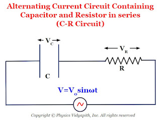
Let us consider, a circuit containing capacitor $C$ resistor $R$ and these are connected in series. If an alternating voltage source is applied across it then the resultant voltage of the C-R circuit
$V=\sqrt{ V_{C} ^{2} + V^{2}_{R}} \qquad(1)$
We know that:
$V_{R} = iR$
$V_{C} = iX_{C}$
So from equation $(1)$
$V=\sqrt{\left( iX_{C} \right)^{2} + \left(iR\right)^{2}} $
$V=i\sqrt{\left( X_{C} \right)^{2} + R^{2}} $
$\frac{V}{i}=\sqrt{\left( X_{C} \right)^{2} + R^{2}} $
$Z=\sqrt{\left( X_{C} \right)^{2} + R^{2}} \qquad(2)$
Where
$Z \rightarrow$ Impedance of C-R circuit.
$X_{C} \rightarrow$ Capacitive Reactance which has value $\frac{1}{\omega C}$
So from equation $(2)$, we get
$Z=\sqrt{\left( \frac{1}{\omega C} \right)^{2} + R^{2}} \qquad(3)$
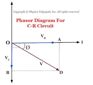
The phase of resultant voltage:
If the phase of resultant voltage from from current is $\phi$ then
$tan \phi = \frac{X_{C} }{R} \qquad(4)$
$tan \phi = \frac{\frac{1}{\omega C}}{R} $
$tan \phi = \frac{1}{\omega C R} $
$\phi = tan^{1} \left(\frac{1}{\omega C R}\right) $
$V_{C} = iX_{C}$
$Z \rightarrow$ Impedance of C-R circuit.
$X_{C} \rightarrow$ Capacitive Reactance which has value $\frac{1}{\omega C}$
Circuit containing Inductor and Resistor in Series (L-R Series Circuit )
Mathematical Analysis of L-R Series Circuit :
Let us consider, a circuit containing inductor $L$ resistor $R$ and these are connected in series. If an alternating voltage source is applied across it then the resultant voltage of the L-R circuit
$V=\sqrt{ V_{L} ^{2} + V^{2}_{R}} \qquad(1)$
We know that:
$V_{R} = iR$
$V_{L} = iX_{L}$
So from equation $(1)$
$V=\sqrt{\left( iX_{L} \right)^{2} + \left(iR\right)^{2}} $
$V=i\sqrt{\left( X_{L} \right)^{2} + R^{2}} $
$\frac{V}{i}=\sqrt{\left( X_{L} \right)^{2} + R^{2}} $
$Z=\sqrt{\left( X_{L} \right)^{2} + R^{2}} \qquad(2)$
Where
$Z \rightarrow$ Impedance of L-R circuit.
$X_{L} \rightarrow$ Inductive Reactance which has value $\omega L$
So from equation $(2)$, we get
$Z=\sqrt{\left( \omega L \right)^{2} + R^{2}} \qquad(3)$
The phase of resultant voltage:
If the phase of resultant voltage from from current is $\phi$ then
$tan \phi = \frac{X_{L} }{R} \qquad(4)$
$tan \phi = \frac{\omega L }{R} $
$\phi = tan^{1} \left(\frac{\omega L }{R}\right) $
$V_{L} = iX_{L}$
$Z \rightarrow$ Impedance of L-R circuit.
$X_{L} \rightarrow$ Inductive Reactance which has value $\omega L$
Circuit containing Inductor, Capacitor, and Resistor in Series (L-C-R Series Circuit )
Mathematical Analysis of L-C-R Series Circuit :
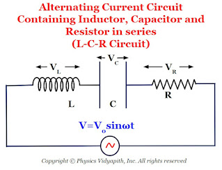
Let us consider, a circuit containing inductor $L$, capacitor $C$, and resistor $R$ and these are connected in series. If an alternating voltage source is applied across it then the resultant voltage of the L-C-R circuit
$V=\sqrt{\left( V_{L} -V_{C} \right)^{2} + V^{2}_{R}} \qquad(1)$
We know that:
$V_{R} = iR$
$V_{L} = iX_{L}$
$V_{C} = iX_{C}$
So from equation $(1)$
$V=\sqrt{\left( iX_{L} - iX_{C} \right)^{2} + (iR)^{2}} $
$V=i\sqrt{\left( X_{L} - X_{C} \right)^{2} + R^{2}} $
$\frac{V}{i}=\sqrt{\left( X_{L} - X_{C} \right)^{2} + R^{2}} $
$Z=\sqrt{\left( X_{L} - X_{C} \right)^{2} + R^{2}} \qquad(2)$
Where
$Z \rightarrow$ Impedance of L-C-R circuit.
$X_{L} \rightarrow$ Inductive Reactance which has value $\omega L$
$X_{C} \rightarrow$ Inductive Reactance which has value $\frac{1}{\omega C}$
So from equation $(2)$, we get
$Z=\sqrt{\left( \omega L - \frac{1}{\omega C} \right)^{2} + R^{2}} \qquad(3)$
The phase of resultant voltage:
If the phase of resultant voltage from from current is $\phi$ then
$tan \phi = \frac{X_{L} - X_{C}}{R} \qquad(4)$
$tan \phi = \frac{\omega L - \frac{1}{\omega C}}{R} $
$ \phi = tan^{-1} \left( \frac{\omega L - \frac{1}{\omega C}}{R} \right) $
The Impedance and Phase at Resonance Condition:($X_{L} = X_{C}$):
At resonance $X_{L} = X_{C} \qquad(5)$
$\omega L = \frac{1}{\omega C}$
$\omega^{2} = \frac{1}{L C}$
$\omega = \sqrt{\frac{1}{L C}}$
$2 \pi f = \sqrt{\frac{1}{L C}}$
$ f = \frac{1}{2 \pi}\sqrt{\frac{1}{L C}}$
Where $f \rightarrow$ Natural frequency of the circuit
1.) The Impedance of the circuit at resonance condition:
Substitute the resonance condition i.e. $X_{L} = X_{C}$ in equation $(2)$ then the impedance of the L-C-R Circuit
$Z=R$
The impedance of the L-C-R circuit at resonance condition is equal to the resistance of the resistor applied in a circuit.
2.) The Phase of resultant voltage at resonance condition:
$tan\phi =0$
$tan\phi = tan 0^{\circ}$
$\phi=0^{\circ}$
The phase of resultant voltage at resonance condition is zero. i.e. the direction of resultant voltage in the direction of current in the circuit.
Note: There are following cases arise in the L-C-R circuit at resonance condition
Case -1:
If $X_{L} \gt X_{C}$, the $tan \phi$ is positive, i.e. $\phi$ is positive. In this case, the voltage leads to the current. Therefore, the circuit is more inductive rather than capacitive or resistive.
Case -2:
If $X_{L} \lt X_{C}$, the $tan \phi$ is negative, i.e. $\phi$ is negative. In this case, the voltage lags behind the current. Therefore, the circuit has a more capacitance-dominated circuit.
Case -3:
If $X_{L} = X_{C}$, the $tan \phi$ is zero, i.e. $\phi$ is negative. In this case, the voltage and the current are in phase. Therefore, the circuit is purely resistive.
$V_{L} = iX_{L}$
$V_{C} = iX_{C}$
$Z \rightarrow$ Impedance of L-C-R circuit.
$X_{L} \rightarrow$ Inductive Reactance which has value $\omega L$
$X_{C} \rightarrow$ Inductive Reactance which has value $\frac{1}{\omega C}$
Merits and Demerits of Alternating Current in Comparison to Direct Current
Merits and Demerits of AC in Comparison to DC
(a) Merits
(i) Alternating current can be increased or decreased by using a transformer.
This is the reason that Alternating current can be transmitted from one place to other place at relatively lower expenditure and minimum loss of energy. In Direct current, it is not possible.
(ii) Alternating current can be controlled by choke coil or capacitor at very small loss of energy. To control Direct current resistance is required in which energy loss is very high.
(ii) Alternating current can easily be converted into Direct current by using a rectifier but converting Direct current into Alternating current is not easy.
(iv) Alternating current is cheaper than DC. (life of a cell or battery is very limited).
(b) Demerits
(i) Alternating current is more dangerous as compared to Direct current.
(ii) Alternating current cannot be used in electrolysis.
(iii) Most of the Alternating current of high frequency flows on the surface of the wire, therefore, a thick wire by joining number of thin insulated wires in parallel are to be used.
Power in Alternating Current Circuit
Definition of Power in Alternating Current Circuit:
The rate of power consumption in an alternating current circuit is known as power in the circuit.
Mathematical Analysis:
Let us consider an alternating current circuit in which the voltage and current at any instant are given by
$V=V_{\circ} sin \omega t \qquad(1)$
$i=i_{\circ} sin \left( \omega t - \phi \right) \qquad(2)$
Where $\phi$ $\rightarrow$ Phase difference between voltage and current
So instantaneous Power
$P=Vi$
$P=\left\{V_{\circ} sin \omega t \right\} \left\{ i_{\circ} sin \left( \omega t - \phi \right) \right\}$
$P=V_{\circ} i_{\circ} \: sin \omega t \: sin \left( \omega t - \phi \right)$
$P=\frac{V_{\circ} i_{\circ}}{2} \left[2\: sin \: \omega t \: sin \left( \omega t - \phi \right)\right]$
$P=\frac{V_{\circ} i_{\circ}}{2} \left[ cos \left( \omega t -\omega t + \phi \right) \\ \qquad - cos \left( \omega t + \omega t - \phi \right) \right]$
$P=\frac{V_{\circ} i_{\circ}}{2} \left[ cos \left(\phi \right) - cos \left( 2\omega t - \phi \right) \right]$
The average power for one cycle is:
$P_{avg}$ = The average value of $\left\{ \frac{V_{\circ} i_{\circ}}{2} \left[ cos \left(\phi \right) - cos \left( 2\omega t - \phi \right) \right] \right\}$
The term $cos \left( 2\omega t - \phi \right)$ is time-dependent and the average value of term $cos \left( 2\omega t - \phi \right)$ for complete one cycle is zero. So the average power dissipation in one cycle is
$P_{avg}= \frac{V_{\circ} i_{\circ}}{2} cos \phi $
$P_{avg}= \frac{V_{\circ}}{\sqrt{2}} \frac{i_{\circ}}{\sqrt{2}} cos \phi $
$P_{avg}= V_{rms} \: i_{rms} cos \phi $
Case -1 The circuit containing Pure Resistor only:
If the circuit contains a pure resistance only then voltage $V$ and current $i$ are always in the same phase. i.e. $\phi=0^{\circ}$ and $cos \phi = +1$, then average power
$P_{avg}= V_{rms} \: i_{rms} $
Case -2 The circuit containing Pure Inductor only:
If the circuit containing pure inductor only then voltage $V$ leads over current $i$ by $90^{\circ}$ i.e. $\phi=90^{\circ}$ and $cos 90^{\circ} = 0$, then average power
$P_{avg}= 0 $
Case -3 The circuit containing Pure Capacitor only:
If the circuit containing pure capacitor only then voltage $V$ lags behind current $i$ by $90^{\circ}$ i.e. $\phi=90^{\circ}$ and $cos 90^{\circ} = 0$, then average power
$P_{avg}= 0 $
Case -4 The circuit containing inductor and resistor only (L-R Circuit):
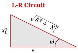
We know that the phase in the L-R circuit is
$tan \phi = \frac{X_{L}}{R}$
From the above equation, Draw the triangle as shown in the figure below:
From the above figure, the value of $cos\phi$ is
$cos \phi = \frac{R}{\sqrt{R^{2} + X^{2}_{L}}}$
So average power
$P_{avg}= V_{rms} \: i_{rms} \frac{R}{\sqrt{R^{2} + X^{2}_{L}}} $
$\left(P_{avg}\right)_{L-R} \lt \left(P_{avg}\right)_{R}$
Thus, the average power consumption in an L-R circuit is less than the power consumed in a purely resistive circuit
Case -5 The circuit containing capacitor and resistor only (C-R Circuit):
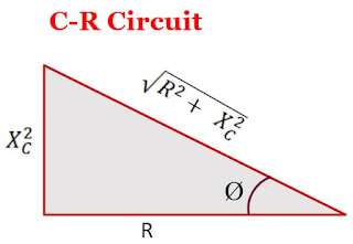
We know that the phase in the C-R circuit is
$tan \phi = \frac{X_{C}}{R}$
From the above equation, Draw the triangle as shown in the figure below:
From the above figure, the value of $cos\phi$ is
$cos \phi = \frac{R}{\sqrt{R^{2} + X^{2}_{C}}}$
So average power
$P_{avg}= V_{rms} \: i_{rms} \frac{R}{\sqrt{R^{2} + X^{2}_{C}}} $
$\left(P_{avg}\right)_{C-R} \lt \left(P_{avg}\right)_{R}$
Thus, the average power consumption in a C-R circuit is less than the power consumed in a purely resistive circuit
Case -6 The circuit containing capacitor and inductor only (L-C Circuit):
We know that the phase in the L-R circuit is
$\phi = 90^{\circ}$ and $cos 90^{\circ} = 0$
So average power
$P_{avg}= 0 $
Case -7 The circuit containing inductor, capacitor, and resistor only (L-C-R Circuit):
We know that the phase in the L-C-R circuit is
$tan \phi = \frac{X_{L} - X_{C}}{R}$
From the above equation, Draw the triangle as shown in the figure below:
From the above figure, the value of $cos\phi$ is
$cos \phi = \frac{R^{2}}{\sqrt{R^{2} + \left( X^{2}_{L} - X^{2}_{C} \right) }}$
So average power
$P_{avg}= V_{rms} \: i_{rms} \frac{R^{2}}{\sqrt{R^{2} + \left( X^{2}_{L} - X^{2}_{C} \right) }} $
$\left(P_{avg}\right)_{L-C-R} \lt \left(P_{avg}\right)_{R}$
Thus, the average power consumption in an L-C-R circuit is less than the power consumed in a purely resistive circuit
Wattless Current:
If the circuit contains only resistor or only inductor or only inductor and capacitor then power consumption in the circuit will be zero (i.e. there will be no energy dissipation in the circuit) due to the phase difference $90^{\circ}$ between voltage(or impedance) and current. So the current in the circuit is called the "Wattless current".
Self Induction Phenomenon and its Coefficient
Self Induction:
When a changing current flows in a coil then due to the change in magnetic flux in the coil produces an electro-motive force $\left(emf \right)$ in that coil. This phenomenon is called the principle of Self Induction.
The direction of electro-motive force can be found by applying "Lenz's Law".
Mathematical Analysis of Coefficient of Self Induction:
Let us consider that a coil having the number of turns is $N$. If the change in current is $i$, then linkage flux in a coil will be
$N \phi \propto i$
$N\phi = L i \qquad(1)$
Where $L$ $\rightarrow$ Coefficient of Self Induction.
According to Faraday's law of electromagnetic induction. The electro-motive force $\left(emf \right)$ in a coil is
$e=-N\left( \frac{d \phi}{dt} \right)$
$e=-\frac{d \left(N \phi \right)}{dt} \qquad(2)$
From equation $(1)$ and equation $(2)$
$e=-\frac{d \left(L i\right)}{dt} $
$e=-L \left(\frac{d i}{dt} \right) $
$L = \frac{e}{\left(\frac{d i}{dt} \right)}$
If $\left(\frac{d i}{dt} \right) = 1$
Then
$L = e$
The above equation shows that If the rate of flow of current in a coil is unit then the coefficient of self-induction in that coil will be equal to the induced electro-motive force $\left( emf \right)$.
Popular Posts
-
Angle of Acceptance → "If incident angle of light on the core for which the incident angle on the core-cladding interface equals t...
-
Let $S$ be a point monochromatic source of light of wavelength $\lambda$ placed at the focus of collimating lens $L_{1}$. The light beam is ...
-
Maxwell's Equations: Maxwell's equation of the electromagnetic wave is a collection of four equations i.e. Gauss's law of elec...
-
Derivation of interference of light due to a wedge-shaped thin film: Interference of light due to wedge-shaped thin film The wedge...
-
Let a plane wavefront be incident normally on slit $S_{1}$ and $S_{2}$ of equal $e$ and separated by an opaque distance $d$.The diffracted l...
Study-Material
Categories
Alternating Current Circuits
(10)
Atomic and Molecular Physics
(4)
Biomedical
(1)
Capacitors
(6)
Classical Mechanics
(12)
Current carrying loop in magnetic field
(5)
Current Electricity
(10)
Dielectric Materials
(1)
Electromagnetic Induction
(3)
Electromagnetic Wave Theory
(23)
Electrostatic
(22)
Energy Science and Engineering
(2)
Error and Measurement
(2)
Gravitation
(10)
Heat and Thermodynamics
(3)
Kinematics Theory Of Gases
(2)
Laser System & Application
(15)
Magnetic Effect of Current
(9)
Magnetic Substances
(3)
Mechanical Properties of Fluids
(4)
Nanoscience & Nanotechnology
(4)
Nuclear Physics
(7)
Numerical Problems and Solutions
(1)
Optical Fibre
(5)
Optics
(25)
Photoelectric Effect
(3)
Quantum Mechanics
(33)
Relativity
(8)
Semiconductors
(2)
Superconductors
(1)
Topic wise MCQ
(9)
Units and Dimensions
(1)
Waves
(5)
