Combined Focal Length and Power of two thin lenses in contact

Derivation of the combined focal length and power of two thin lenses in contact:

Case (1): When both are convex lens-

a.) The combined focal length of two thin convex lenses in contact:

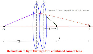
Let us consider that two convex lenses $L_{1}$ and $L_{2}$ are connected with transparent cement Canada Balsam. If the focal length of the lenses is $f_{1}$ and $f_{1}$ and an object $O$ is placed at distance $u$ from the first lens $L_{1}$ and its image $I'$ is formed at a distance $v'$ from the first lens $L_{1}$. Therefore from the equation of focal length for lens $L_{1}$
Refraction of light through two combined convex lens
$\frac{1}{f_{1}} = \frac{1}{v'} - \frac{1}{u} \qquad(1)$

For the second lens, The image $I'$ works as a virtual object for the second lens $L_{2}$ which image $I$ is formed at a distance $v$ from the second lens $L_{2}$. Therefore from the equation of focal length for lens $L_{2}$

$\frac{1}{f_{2}} = \frac{1}{v} - \frac{1}{v'} \qquad(2)$

Now add the equation $(1)$ and equation $(2)$. then

$\frac{1}{f_{1}} + \frac{1}{f_{2}} = \frac{1}{v'} - \frac{1}{u} + \frac{1}{v} - \frac{1}{v'} $

$\frac{1}{f_{1}} + \frac{1}{f_{2}} = \frac{1}{v} - \frac{1}{u} $

Where $ \frac{1}{f} = \frac{1}{v} - \frac{1}{u} $

$\frac{1}{f_{1}} + \frac{1}{f_{2}} = \frac{1}{f} \qquad(3)$

$\frac{1}{f} = \frac{f_{1} + f_{2}}{f_{1}f_{2}} $

$f = \frac{f_{1}f_{2}}{f_{1} + f_{2}} $

This is the equation of the combined focal length of two thin convex lenses in contact.

b.)The combined power of two thin convex lenses in contact:

We know that the power of the lens equation

$P = \frac{1}{f}$

So from equation $(3)$

$P=P_{1} + P_{2}$

This is the equation of the combined power of two thin convex lenses in contact.

Similarly for another two cases $(2)$ and case $(3)$:

Case (2): When both are concave lens-

a.) The combined focal length of two thin concave lenses in contact:

For concave lenses the focal length for both lenses i.e. ($f_{1} \: and \: f_{2}$) will be negative. Therefore the combined focal length of the two thin concave lens

$ \frac{1}{f} = \frac{1}{- f_{1}} + \frac{1}{- f_{2}} $

$\frac{1}{f} =- \frac{\left(f_{1} + f_{2} \right)}{f_{1}f_{2}} $

$f = -\frac{f_{1}f_{2}}{f_{1} + f_{2}} $
Refraction of light through two combined concave lens
b.) The combined power of two thin concave lenses in contact:

$P= - \left(P_{1} + P_{2}\right)$

Case (3): When one lens is convex and the second is concave-

a.) The combined focal length of two thin lenses for convex and concave:

If the focal length of convex lens is $f_{1}$ and for concave is $f_{2}$ then the combine focal length of lenses

$ \frac{1}{f} = \frac{1}{ f_{1}} + \frac{1}{- f_{2}} $

$\frac{1}{f} = \frac{\left(f_{1} - f_{2} \right)}{f_{1}f_{2}} $

$f = \frac{f_{1}f_{2}}{f_{1} - f_{2}} $
Refraction of light through two combined convex and concave lens
b.) The combined power of two thin lenses for convex and concave:

$P= \left(P_{1} - P_{2}\right)$
Comments

Popular Posts

Numerical Aperture and Acceptance Angle of the Optical Fibre

Angle of Acceptance → If incident angle of light on the core for which the incident angle on the core-cladding interface equals the critical angle then incident angle of light on the core is called the "Angle of Acceptance. Transmission of light when the incident angle is equal to the acceptance angle If the incident angle is greater than the acceptance angle i.e. $\theta_{i}>\theta_{0}$ then the angle of incidence on the core-cladding interface will be less than the critical angle due to which part of the incident light is transmitted into cladding as shown in the figure below Transmission of light when the incident angle is greater than the acceptance angle If the incident angle is less than the acceptance angle i.e. $\theta_{i}<\theta_{0}$ then the angle of incidence on the core-cladding interface will be greater than the critical angle for which total internal reflection takes place inside the core. As shown in the figure below Transmission of lig

Fraunhofer diffraction due to a single slit

Let $S$ be a point monochromatic source of light of wavelength $\lambda$ placed at the focus of collimating lens $L_{1}$. The light beam is incident normally from $S$ on a narrow slit $AB$ of width $e$ and is diffracted from it. The diffracted beam is focused at the screen $XY$ by another converging lens $L_{2}$. The diffraction pattern having a central bright band followed by an alternative dark and bright band of decreasing intensity on both sides is obtained. Analytical Explanation: The light from the source $S$ is incident as a plane wavefront on the slit $AB$. According to Huygens's wave theory, every point in $AB$ sends out secondary waves in all directions. The undeviated ray from $AB$ is focused at $C$ on the screen by the lens $L_{2}$ while the rays diffracted through an angle $\theta$ are focussed at point $p$ on the screen. The rays from the ends $A$ and $B$ reach $C$ in the same phase and hence the intensity is maximum. Fraunhofer diffraction due to

Particle in one dimensional box (Infinite Potential Well)

Let us consider a particle of mass $m$ that is confined to one-dimensional region $0 \leq x \leq L$ or the particle is restricted to move along the $x$-axis between $x=0$ and $x=L$. Let the particle can move freely in either direction, between $x=0$ and $x=L$. The endpoints of the region behave as ideally reflecting barriers so that the particle can not leave the region. A potential energy function $V(x)$ for this situation is shown in the figure below. Particle in One-Dimensional Box(Infinite Potential Well) The potential energy inside the one -dimensional box can be represented as $\begin{Bmatrix} V(x)=0 &for \: 0\leq x \leq L \\ V(x)=\infty & for \: 0> x > L \\ \end{Bmatrix}$ $\frac{d^{2} \psi(x)}{d x^{2}}+\frac{2m}{\hbar^{2}}(E-V)\psi(x)=0 \qquad(1)$ If the particle is free in a one-dimensional box, Schrodinger's wave equation can be written as: $\frac{d^{2} \psi(x)}{d x^{2}}+\frac{2mE}{\hbar^{2}}\psi(x)=0$ $\frac{d^{2} \psi(x)}{d x