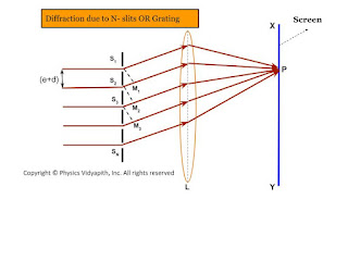
A diffraction grating (or $N$-slits) consists of a large number of parallel slits of equal width and separated from each other by equal opaque spaces.
It may be constructed by ruling a large number of parallel and equidistance lines on a plane glass plate with the help of a diamond point. the duplicates of the original grating are prepared by pouring a thin layer of colloidal solution over it and then allowed to Harden. This layer is then removed from the original grating and fixed between two glass plates which serve as a plane transmission grating. Generally, A plane transmission grating has 10000 to 15000 lines per inch.
 |
| Diffraction due to N- slits OR Grating |
Theory→
Since plane diffraction grating is an $N$-slit arrangement, the deflection pattern due to it will be the combined diffraction effect of all such slits. Let a plane wavefront of monochromatic light be incident normally on the $N$-parallel slit of the gratings. Each point within the slits then sends out secondary wavelets in all directions.
Let $e$ be the width of each slipped and $d$ be the separation between any two consecutive slits then $(e+d)$ is known as the grating element. The diffracted ray from each slit, then $(e+d)$ is knowns as the grating element. The diffracted ray from each slit is focussed at a point $P$ on the screen $XY$ with the help of a convex lens $L$.
Expression for Intensity→
Let $S_{1}, S_{2}, S_{3},.......$ be the middle point of each slit and $S_{1}M_{1}, S_{2}M_{2}, S_{3}M_{3}, ........S_{N-1}M_{N-1}$ be the perpendicular drawn as shown in the figure.The waves diffracted from each slit are equivalent to a single wave amplitude:
$R=\frac{A\:sin\alpha}{\alpha} \qquad(1)$
The path difference between the waves from slit $S_{1}$ and $S_{2}$ is
$S_{2}M_{1}=(e+d)sin\theta$
The path difference between the waves from slit $S_{2}$ and $S_{3}$ is
$S_{3}M_{2}=(e+d)sin\theta$
The path difference between the waves from slit $S_{n-1}$ and $S_{n}$ is
$S_{N}M_{N-1}=(e+d)sin\theta$
Thus, it is obvious that the path difference between all the consecutive waves is the same and equal to $(e+d)sin\theta$
The corresponding phase difference
$\Delta \phi=\frac{2\pi}{\lambda}(e+d)sin\theta \qquad(2)$
Let $\Delta \phi=2\beta$
$\beta=\frac{\pi}{\lambda}(e+d)sin\theta \qquad(3)$
Thus, the resultant amplitude at $P$ is the resultant amplitude of $N$ waves, each of amplitude $R$ and its common phase difference is $(2\beta)$
$R'=\frac{R \: sin \left( \frac{2N\beta}{2} \right) }{sin \left( \frac{2\beta}{2} \right)} \qquad(4)$
The resultant amplitude at $P$
$R'=\frac{R \: sin N\beta}{sin \beta} $
Where $R=\frac{A\: sin\alpha}{\alpha}$. Now substitute the value of $R$ in the above equation and we get
$R'= \frac{A\: sin\alpha}{\alpha} \frac{ \: sin N\beta}{sin \beta} \qquad(5)$
The resultant intensity at $P$
$I=R'^{2}$
$I=\frac{A^{2} \: sin^{2} \alpha}{\alpha^{2}} \frac{ \: sin^{2} N\beta}{sin^{2} \beta} \qquad(6)$
The factor $\frac{A^{2} \: sin^{2} \alpha}{\alpha^{2}}$ gives the intensity pattern due to diffraction from a single slit while the factor $\frac{ \: sin^{2} N\beta}{sin^{2} \beta}$ gives the distribution of intensity due to interference from all the $N$-slit
Principle Maxima→
The intensity will be maximum when $sin\beta=0$ or $\beta=\pm n\pi$
Where $n=0,1,2,3,.....$
But under this condition, $sinN\beta$ is also equal to zero. Hence term $\frac{sin N\beta}{sin \beta}$ can be solve by
$\lim_{\beta \rightarrow \pm n\pi} \frac{ \: sin N\beta}{sin \beta}=\lim_{\beta \rightarrow \pm n\pi} \frac{\frac{d}{d\beta} (sin N\beta)}{\frac{d}{d\beta}(sin \beta)}$
$\lim_{\beta \rightarrow \pm n\pi} \frac{ \: sin N\beta}{sin \beta}=\lim_{\beta \rightarrow \pm n\pi} \frac{N cos N\beta}{cos \beta}$
$\lim_{\beta \rightarrow \pm n\pi} \frac{ \: sin N\beta}{sin \beta}=N \lim_{\beta \rightarrow \pm n\pi} \frac{ cos N\beta}{cos \beta}$
Where the value of $\lim_{\beta \rightarrow \pm n\pi} \frac{ cos N\beta}{cos \beta}=1$
$\lim_{\beta \rightarrow \pm n\pi} \frac{ \: sin N\beta}{sin \beta}=N \qquad(7)$
So the maximum intensity
$I=\frac{A^{2} \: sin^{2} \alpha}{\alpha^{2}} N^{2} \qquad(8)$
Thus, the condition for principle maxima
$sin \beta=0$
$\beta=\pm n\pi$
$(e+d)sin\theta=\pm n \lambda \qquad(9)$
For $n=0$, we get $\theta=0$ This $\theta=0$ gives the direction of zero-order principal maxima. For the value of $n=1,2,3,......$, gives the direction of first, second, third,....... order principal maxima.
Minima →
The intensity will be minimum, when $sin N\beta=0$ but $sin\beta=0$
$N\beta=\pm m\pi$
$N(e+d)sin\theta=\pm m \lambda \qquad(10)$
Where $m$ can take all integral values except $0, N,2N,3N,......$ because for these values of $m$, $sin\beta=0$ which gives the position of principal maxima.
Secondary maxima→
It is obvious from the above condition of minima, there are $(N-1)$ minima between two successive principal maxima. Hence, there are $(N-2)$ other maxima with alternative minima between two successive principal maxima. These $(N-2)$ maxima are called secondary maxima. To find the condition of secondary maxima equation $(6)$ is differentiated with respect to $\beta$ and equated to zero.
$\frac{dI}{d\beta}= \frac{A^{2}\:sin^{2}\alpha}{\alpha^{2}}2 \frac{sinN\beta}{sin\beta} \left [\frac{sin\beta . N. cosN\beta-sinN\beta . cos\beta}{sin^{2}\beta} \right ]$
$0= \frac{A^{2}\:sin^{2}\alpha}{\alpha^{2}}2 \frac{sinN\beta}{sin\beta} \left [\frac{sin\beta . N. cosN\beta-sinN\beta . cos\beta}{sin^{2}\beta} \right ]$
$N.sin\beta . cosN\beta - sinN \beta . cos\beta=0$
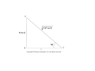
$\tan N\beta = N tan \beta \qquad(11)$
Now construct a right-angled triangle with the sides according to the above equation$(11)$
 |
| Right-angled Triangle for Intensity Calculation |
From the above triangle:
$sinN\beta=\frac{N tan\beta}{\sqrt{1+N^{2}tan^{2}\beta}} \qquad(12)$
Substituting the value of $sinN\beta$ from the above equation to equation (6)
$I=\frac{A^{2} \: sin^{2} \alpha}{\alpha^{2}} \frac{N^{2} tan^{2}\beta}{1+N^{2}tan^{2}\beta} \frac{ 1}{sin^{2} \beta}$
$I=\frac{A^{2} \: sin^{2} \alpha}{\alpha^{2}} \frac{N^{2}}{1+N^{2}tan^{2}\beta} \frac{ 1}{cos^{2} \beta} \qquad \left(\because tan\beta =\frac{sin\beta}{cos\beta} \right)$
$I=\frac{A^{2} \: sin^{2} \alpha}{\alpha^{2}} \frac{N^{2}}{cos^{2} \beta+N^{2}sin^{2}\beta} $
$I=\frac{A^{2} \: sin^{2} \alpha}{\alpha^{2}} \frac{N^{2}}{1- sin^{2} \beta+N^{2}sin^{2}\beta} $
$I=\frac{A^{2} \: sin^{2} \alpha}{\alpha^{2}} \frac{N^{2}}{1+(N^{2}-1) sin^{2} \beta} \qquad(12)$
Now divide the equation $(12)$ by equation $(8)$ so
$\frac{Intensity\: of\:secondary\:maxima}{Intensity\:of\:principal\:maxima}=\frac{1}{1+(N^{2}-1) sin^{2} \beta}$
It is obvious from the above equation that When $N$ increases then the intensity of secondary maxima decreases.
 |
| Intensity distribution diagram due to a diffraction grating |


