Showing posts with label Alternating Current Circuits. Show all posts

Circuit containing Inductor and Capacitor in Series (L-C Series Circuit )

Mathematical Analysis of L-C Series Circuit :
Alternating Current Circuit Containing Inductor and Capacitor in series
Let us consider, a circuit containing inductor $L$ capacitor $C$ and these are connected in series. If an alternating voltage source is applied across it then the resultant voltage of the L-C circuit

$V=V_{L} - V_{C} \qquad(1)$

We know that:

$V_{L} = iX_{L}$
$V_{C} = iX_{C}$

So from equation $(1)$

$V= iX_{L} - iX_{C} $

$V=i \left(X_{L} - X_{C} \right) $

$\frac{V}{i}=\left(X_{L} - X_{C} \right) $

$Z=\left(X_{L} - X_{C} \right) \qquad(2)$

Where
$Z \rightarrow$ Impedance of L-C circuit.
$X_{L} \rightarrow$ Inductive Reactance which has value $\omega L$
$X_{C} \rightarrow$ Capacitive Reactance which has value $\frac{1}{\omega C}$

So from equation $(2)$, we get

$Z=\left( \omega L - \frac{1}{\omega C} \right) \qquad(3)$

The phase of resultant voltage:
Phasor Diagram For L-C Circuit
The phase of resultant voltage from current is $90^{\circ}$ as shown in the figure above.

The Impedance and Phase at Resonance Condition:($X_{L} = X_{C}$):

At resonance $X_{L} = X_{C} \qquad(5)$

$\omega L = \frac{1}{\omega C}$

$\omega^{2} = \frac{1}{L C}$

$\omega = \sqrt{\frac{1}{L C}}$

$2 \pi f = \sqrt{\frac{1}{L C}}$

$ f = \frac{1}{2 \pi}\sqrt{\frac{1}{L C}}$

Where $f \rightarrow$ Natural frequency of the circuit.

1.) The Impedance of the circuit at resonance condition:

Substitute the resonance condition i.e. $X_{L} = X_{C}$ in equation $(2)$ then the impedance of the L-C Circuit

$Z=0$

The impedance of the L-C circuit at resonance condition is zero.

2.) The Phase of resultant voltage at resonance condition:

There is not any change in the phase of resultant voltage at resonance condition i.e. that will be the same $90^{\circ}$.

Circuit containing Capacitor and Resistor in Series (C-R Series Circuit )

Mathematical Analysis of C-R Series Circuit :
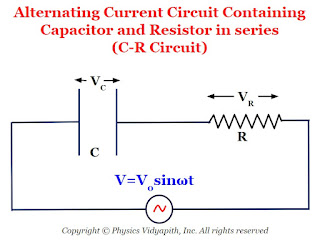
Alternating Current Circuit Containing Capacitor and Resistor in series
Let us consider, a circuit containing capacitor $C$ resistor $R$ and these are connected in series. If an alternating voltage source is applied across it then the resultant voltage of the C-R circuit

$V=\sqrt{ V_{C} ^{2} + V^{2}_{R}} \qquad(1)$

We know that:

$V_{R} = iR$
$V_{C} = iX_{C}$

So from equation $(1)$

$V=\sqrt{\left( iX_{C} \right)^{2} + \left(iR\right)^{2}} $

$V=i\sqrt{\left( X_{C} \right)^{2} + R^{2}} $

$\frac{V}{i}=\sqrt{\left( X_{C} \right)^{2} + R^{2}} $

$Z=\sqrt{\left( X_{C} \right)^{2} + R^{2}} \qquad(2)$

Where
$Z \rightarrow$ Impedance of C-R circuit.
$X_{C} \rightarrow$ Capacitive Reactance which has value $\frac{1}{\omega C}$

So from equation $(2)$, we get

$Z=\sqrt{\left( \frac{1}{\omega C} \right)^{2} + R^{2}} \qquad(3)$

The phase of resultant voltage:
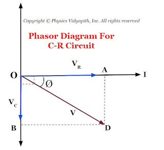
Phasor Diagram For C-R Circuit
If the phase of resultant voltage from from current is $\phi$ then

$tan \phi = \frac{X_{C} }{R} \qquad(4)$

$tan \phi = \frac{\frac{1}{\omega C}}{R} $

$tan \phi = \frac{1}{\omega C R} $

$\phi = tan^{1} \left(\frac{1}{\omega C R}\right) $

Circuit containing Inductor and Resistor in Series (L-R Series Circuit )

Mathematical Analysis of L-R Series Circuit :
Alternating Current Circuit Containing Inductor and Resistor in series
Let us consider, a circuit containing inductor $L$ resistor $R$ and these are connected in series. If an alternating voltage source is applied across it then the resultant voltage of the L-R circuit

$V=\sqrt{ V_{L} ^{2} + V^{2}_{R}} \qquad(1)$

We know that:

$V_{R} = iR$
$V_{L} = iX_{L}$

So from equation $(1)$

$V=\sqrt{\left( iX_{L} \right)^{2} + \left(iR\right)^{2}} $

$V=i\sqrt{\left( X_{L} \right)^{2} + R^{2}} $

$\frac{V}{i}=\sqrt{\left( X_{L} \right)^{2} + R^{2}} $

$Z=\sqrt{\left( X_{L} \right)^{2} + R^{2}} \qquad(2)$

Where
$Z \rightarrow$ Impedance of L-R circuit.
$X_{L} \rightarrow$ Inductive Reactance which has value $\omega L$

So from equation $(2)$, we get

$Z=\sqrt{\left( \omega L \right)^{2} + R^{2}} \qquad(3)$

The phase of resultant voltage:
Phasor Diagram For L-R Circuit
If the phase of resultant voltage from from current is $\phi$ then

$tan \phi = \frac{X_{L} }{R} \qquad(4)$

$tan \phi = \frac{\omega L }{R} $

$\phi = tan^{1} \left(\frac{\omega L }{R}\right) $

Circuit containing Inductor, Capacitor, and Resistor in Series (L-C-R Series Circuit )

Mathematical Analysis of L-C-R Series Circuit :
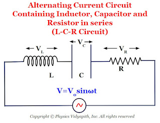
Alternating Current Circuit Containing Inductor, Capacitor and Resistor in series
Let us consider, a circuit containing inductor $L$, capacitor $C$, and resistor $R$ and these are connected in series. If an alternating voltage source is applied across it then the resultant voltage of the L-C-R circuit

$V=\sqrt{\left( V_{L} -V_{C} \right)^{2} + V^{2}_{R}} \qquad(1)$

We know that:

$V_{R} = iR$
$V_{L} = iX_{L}$
$V_{C} = iX_{C}$

So from equation $(1)$

$V=\sqrt{\left( iX_{L} - iX_{C} \right)^{2} + (iR)^{2}} $

$V=i\sqrt{\left( X_{L} - X_{C} \right)^{2} + R^{2}} $

$\frac{V}{i}=\sqrt{\left( X_{L} - X_{C} \right)^{2} + R^{2}} $

$Z=\sqrt{\left( X_{L} - X_{C} \right)^{2} + R^{2}} \qquad(2)$

Where
$Z \rightarrow$ Impedance of L-C-R circuit.
$X_{L} \rightarrow$ Inductive Reactance which has value $\omega L$
$X_{C} \rightarrow$ Inductive Reactance which has value $\frac{1}{\omega C}$

So from equation $(2)$, we get

$Z=\sqrt{\left( \omega L - \frac{1}{\omega C} \right)^{2} + R^{2}} \qquad(3)$

The phase of resultant voltage:
Phasor Diagram For L-C-R Circuit
If the phase of resultant voltage from from current is $\phi$ then

$tan \phi = \frac{X_{L} - X_{C}}{R} \qquad(4)$

$tan \phi = \frac{\omega L - \frac{1}{\omega C}}{R} $

$ \phi = tan^{-1} \left( \frac{\omega L - \frac{1}{\omega C}}{R} \right) $

The Impedance and Phase at Resonance Condition:($X_{L} = X_{C}$):

At resonance $X_{L} = X_{C} \qquad(5)$

$\omega L = \frac{1}{\omega C}$

$\omega^{2} = \frac{1}{L C}$

$\omega = \sqrt{\frac{1}{L C}}$

$2 \pi f = \sqrt{\frac{1}{L C}}$

$ f = \frac{1}{2 \pi}\sqrt{\frac{1}{L C}}$

Where $f \rightarrow$ Natural frequency of the circuit

1.) The Impedance of the circuit at resonance condition:

Substitute the resonance condition i.e. $X_{L} = X_{C}$ in equation $(2)$ then the impedance of the L-C-R Circuit

$Z=R$

The impedance of the L-C-R circuit at resonance condition is equal to the resistance of the resistor applied in a circuit.

2.) The Phase of resultant voltage at resonance condition:

$tan\phi =0$

$tan\phi = tan 0^{\circ}$

$\phi=0^{\circ}$

The phase of resultant voltage at resonance condition is zero. i.e. the direction of resultant voltage in the direction of current in the circuit.

Note: There are following cases arise in the L-C-R circuit at resonance condition

Case -1:

If $X_{L} \gt X_{C}$, the $tan \phi$ is positive, i.e. $\phi$ is positive. In this case, the voltage leads to the current. Therefore, the circuit is more inductive rather than capacitive or resistive.

Case -2:

If $X_{L} \lt X_{C}$, the $tan \phi$ is negative, i.e. $\phi$ is negative. In this case, the voltage lags behind the current. Therefore, the circuit has a more capacitance-dominated circuit.

Case -3:

If $X_{L} = X_{C}$, the $tan \phi$ is zero, i.e. $\phi$ is negative. In this case, the voltage and the current are in phase. Therefore, the circuit is purely resistive.

Merits and Demerits of Alternating Current in Comparison to Direct Current

Merits and Demerits of AC in Comparison to DC

(a) Merits

(i) Alternating current can be increased or decreased by using a transformer.

This is the reason that Alternating current can be transmitted from one place to other place at relatively lower expenditure and minimum loss of energy. In Direct current, it is not possible.

(ii) Alternating current can be controlled by choke coil or capacitor at very small loss of energy. To control Direct current resistance is required in which energy loss is very high.

(ii) Alternating current can easily be converted into Direct current by using a rectifier but converting Direct current into Alternating current is not easy.

(iv) Alternating current is cheaper than DC. (life of a cell or battery is very limited).

(b) Demerits

(i) Alternating current is more dangerous as compared to Direct current.

(ii) Alternating current cannot be used in electrolysis.

(iii) Most of the Alternating current of high frequency flows on the surface of the wire, therefore, a thick wire by joining number of thin insulated wires in parallel are to be used.

Power in Alternating Current Circuit

Definition of Power in Alternating Current Circuit:

The rate of power consumption in an alternating current circuit is known as power in the circuit.

Mathematical Analysis:

Let us consider an alternating current circuit in which the voltage and current at any instant are given by

$V=V_{\circ} sin \omega t \qquad(1)$

$i=i_{\circ} sin \left( \omega t - \phi \right) \qquad(2)$

Where $\phi$ $\rightarrow$ Phase difference between voltage and current

So instantaneous Power

$P=Vi$

$P=\left\{V_{\circ} sin \omega t \right\} \left\{ i_{\circ} sin \left( \omega t - \phi \right) \right\}$

$P=V_{\circ} i_{\circ} \: sin \omega t \: sin \left( \omega t - \phi \right)$

$P=\frac{V_{\circ} i_{\circ}}{2} \left[2\: sin \: \omega t \: sin \left( \omega t - \phi \right)\right]$

$P=\frac{V_{\circ} i_{\circ}}{2} \left[ cos \left( \omega t -\omega t + \phi \right) - cos \left( \omega t + \omega t - \phi \right) \right]$

$P=\frac{V_{\circ} i_{\circ}}{2} \left[ cos \left(\phi \right) - cos \left( 2\omega t - \phi \right) \right]$

The average power for one cycle is:

$P_{avg}=The \: average \: value \: of \left\{ \frac{V_{\circ} i_{\circ}}{2} \left[ cos \left(\phi \right) - cos \left( 2\omega t - \phi \right) \right] \right\}$

The term $cos \left( 2\omega t - \phi \right)$ is time-dependent and the average value of term $cos \left( 2\omega t - \phi \right)$ for complete one cycle is zero. So the average power dissipation in one cycle is

$P_{avg}= \frac{V_{\circ} i_{\circ}}{2} cos \phi $

$P_{avg}= \frac{V_{\circ}}{\sqrt{2}} \frac{i_{\circ}}{\sqrt{2}} cos \phi $

$P_{avg}= V_{rms} \: i_{rms} cos \phi $

Case -1 The circuit containing Pure Resistor only:

If the circuit contains a pure resistance only then voltage $V$ and current $i$ are always in the same phase. i.e. $\phi=0^{\circ}$ and $cos \phi = +1$, then average power

$P_{avg}= V_{rms} \: i_{rms} $

Case -2 The circuit containing Pure Inductor only:

If the circuit containing pure inductor only then voltage $V$ leads over current $i$ by $90^{\circ}$ i.e. $\phi=90^{\circ}$ and $cos 90^{\circ} = 0$, then average power

$P_{avg}= 0 $

Case -3 The circuit containing Pure Capacitor only:

If the circuit containing pure capacitor only then voltage $V$ lags behind current $i$ by $90^{\circ}$ i.e. $\phi=90^{\circ}$ and $cos 90^{\circ} = 0$, then average power

$P_{avg}= 0 $

Case -4 The circuit containing inductor and resistor only (L-R Circuit):

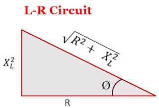
We know that the phase in the L-R circuit is

$tan \phi = \frac{X_{L}}{R}$

From the above equation, Draw the triangle as shown in the figure below:
L-R Circuit Phase Diagram
From the above figure, the value of $cos\phi$ is

$cos \phi = \frac{R}{\sqrt{R^{2} + X^{2}_{L}}}$

So average power

$P_{avg}= V_{rms} \: i_{rms} \frac{R}{\sqrt{R^{2} + X^{2}_{L}}} $

$\left(P_{avg}\right)_{L-R} \lt \left(P_{avg}\right)_{R}$

Thus, the average power consumption in an L-R circuit is less than the power consumed in a purely resistive circuit

Case -5 The circuit containing capacitor and resistor only (C-R Circuit):

We know that the phase in the C-R circuit is

$tan \phi = \frac{X_{C}}{R}$

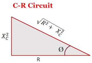
From the above equation, Draw the triangle as shown in the figure below:
C-R Circuit Phase Diagram
From the above figure, the value of $cos\phi$ is

$cos \phi = \frac{R}{\sqrt{R^{2} + X^{2}_{C}}}$

So average power

$P_{avg}= V_{rms} \: i_{rms} \frac{R}{\sqrt{R^{2} + X^{2}_{C}}} $

$\left(P_{avg}\right)_{C-R} \lt \left(P_{avg}\right)_{R}$

Thus, the average power consumption in a C-R circuit is less than the power consumed in a purely resistive circuit

Case -6 The circuit containing capacitor and inductor only (L-C Circuit):

We know that the phase in the L-R circuit is

$\phi = 90^{\circ}$ and $cos 90^{\circ} = 0$

So average power

$P_{avg}= 0 $

Case -7 The circuit containing inductor, capacitor, and resistor only (L-C-R Circuit):

We know that the phase in the L-C-R circuit is

$tan \phi = \frac{X_{L} - X_{C}}{R}$

From the above equation, Draw the triangle as shown in the figure below:
L-C-R Circuit Phase Diagram
From the above figure, the value of $cos\phi$ is

$cos \phi = \frac{R^{2}}{\sqrt{R^{2} + \left( X^{2}_{L} - X^{2}_{C} \right) }}$

So average power

$P_{avg}= V_{rms} \: i_{rms} \frac{R^{2}}{\sqrt{R^{2} + \left( X^{2}_{L} - X^{2}_{C} \right) }} $

$\left(P_{avg}\right)_{L-C-R} \lt \left(P_{avg}\right)_{R}$

Thus, the average power consumption in an L-C-R circuit is less than the power consumed in a purely resistive circuit

Wattless Current:

If the circuit contains only resistor or only inductor or only inductor and capacitor then power consumption in the circuit will be zero (i.e. there will be no energy dissipation in the circuit) due to the phase difference $90^{\circ}$ between voltage(or impedance) and current. So the current in the circuit is called the "Wattless current".

Alternating Current Circuit containing Capacitance only (C-Circuit)

Alternating Current Circuit Containing Capacitance Only (C-Circuit): Let us consider, A circuit containing a capacitor of capacitance $C$ only which is connected with an alternating EMF i.e electromotive force source i.e.
Alternating Current Circuit Containing Capacitance only
Let us consider, A circuit containing a coil of inductance $L$ only which is connected with an alternating EMF i.e electromotive force source i.e.

$E=E_{\circ}sin\omega t\qquad(1)$

When alternating emf is applied across the capacitor plates then the charge on capacitor plates varies continuously and correspondingly current flows in the connecting leads. Let the charge on the capacitor plates is $q$ and the current in the circuit at any instant is $i$. Since there is no resistance in the circuit then the instantaneous potential difference is $\frac{q}{C}$ across the capacitor plates must be equal to the applied emf i.e.

$\frac{q}{C} = E_{\circ} sin \omega t$

$q = CE_{\circ} sin \omega t \qquad(2)$

The instantaneous current $i$ in the circuit is, therefore

$i=\frac{dq}{dt} \qquad(3)$

Now substitute the value of $q$ from equation $(2)$ to equation $(3)$

$i=\frac{d}{dt} CE_{\circ} sin \omega t $

$i=CE_{\circ} \omega cos\omega t$

$i=\omega CE_{\circ} cos\omega t$

$i=\frac{E_{\circ}}{\frac{1}{\omega C}} cos\omega t$

$i=\frac{E_{\circ}}{X_{C}} cos\omega t$

Where $X_{C}= \frac{1}{\omega C}$ is known as capacitive reactance.

$i=i_{\circ} cos\omega t \qquad(4)$

Where the $i_{\circ}=\frac{E_{\circ}}{X_{C}}$ is the maximum current in the circuit. Now apply Ohm's law in this equation and we find that the term $X_{C}=\frac{1}{\omega C}$ has the dimension of resistance. It represents the 'effective opposition' of the capacitor to the flow of alternating current. It is known as the 'reactance of the capacitor' or 'capacitive reactance' and is denoted by $X_{C}$. The capacitive reactance is infinite for DC for which $f=0$.

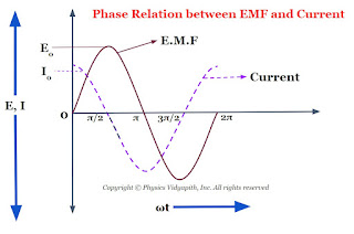
$i=i_{\circ} sin \left( \omega t + \frac{\pi}{2} \right) \qquad(4)$

Now compare equation $(1)$ and equation $(4)$ which shows that an alternating circuit containing a capacitor only, the current leads the emf by a phase angle of $\frac{\pi}{2}$ or $90^\circ$ (or the emf lags behind the current by a phase angle of $\frac{\pi}{2}$). The phase diagram between EMF and the current of a capacitor is shown below-
Phase Relation between EMF and Current of a Capacitor
The phasor diagram between the EMF and current of a capacitor is also shown in the given figure below-
Phasor Diagram between EMF and Current of a capacitor

Alternating Current Circuit containing Inductance only (L-Circuit)

Alternating Current Circuit Containing Inductance only (L-Circuit): Let us consider, An alternating current circuit containing a coil of inductance $L$ only. This inductor is connected with an alternating EMF i.e electromotive force source i.e.
Alternating Current Circuit Containing Inductance only
$E=E_{\circ}sin\omega t\qquad(1)$

The current $i$ in coil varies continuously then an opposite emf is induced in the coil whose magnitude is $L\frac{di}{dt}$ So the net instantaneous of the circuit:

$E_{\circ}sin\omega t -L\frac{di}{dt}=0$

$E_{\circ}sin\omega t =L\frac{di}{dt}$

$di=\frac{E_{\circ}}{L}sin\omega dt$

Now integrate the above equation then the above equation can be written as

$\int di=\int \frac{E_{\circ}}{L}sin\omega dt$

$\int di= \frac{E_{\circ}}{L} \int sin\omega dt$

$i= \frac{E_{\circ}}{L} \frac{-cos\omega t}{\omega}$

$i= -\frac{E_{\circ}}{\omega L} cos\omega t$

$i= -\frac{E_{\circ}}{X_{L}} cos\omega t$

Where $X_{L}= \omega L$ is known as inductive reactance.

$i= -i_{\circ} cos\omega t$

Where $i_{\circ}=\frac{E_{\circ}}{X_{L}}$ is known as the maximum value of current in the circuit. Now compare this equation to Ohm's law then we find that the term $X_{L}=\omega L$ has the dimensions of resistance. It defines the 'effective opposition' of the coil to the flow of alternating current. it is known as the 'reactance of the coil' or 'inductive reactance' and it is denoted by $X_{L}$. The inductive reactance $X_{L}$ is zero for DC at which frequency is zero.

$i= -i_{\circ} sin \left(\frac{\pi}{2}- \omega t \right)$

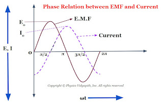
$i= i_{\circ} sin \left(\omega t - \frac{\pi}{2} \right) \qquad(2)$

Now compare equation $(1)$ and equation $(2)$ which shows that an alternating circuit containing an inductor only, the current lags behind the emf by a phase angle of $\frac{\pi}{2}$ or $90^\circ$ (or the emf leads the current by a phase angle of $\frac{\pi}{2}$). The phase diagram between EMF and the current of an inductor is shown below-
Phase Relation between EMF and Current of an Inductor
The phasor diagram between the EMF and current of an inductor is also shown in the given figure below-
Phasor Diagram between EMF and Current of an Inductor

Alternating Current Circuit containing Resistance only (R-Circuit)

Alternating Current Circuit containing Resistance (R-Circuit): Let us consider, An alternating current circuit containing resistance $R$ only. This resistance $R$ is connected with an alternating EMF i.e electromotive force source i.e.
Alternating Current Circuit Containing Resistance only
$E=E_{\circ}sin\omega t\qquad(1)$

The potential difference across the circuit

$E=iR$

Then from equation $(1)$

$iR=E_{\circ}sin\omega t $

$i=\frac{E_{\circ}}{R}sin\omega t $

$i=i_{\circ}sin\omega t \qquad(2) $

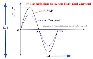
Where $i_{\circ}$ is the peak value or amplitude of the current in the circuit which has value $i_{\circ}=\frac{E_{\circ}}{R}$.

Now compare the equation $(1)$ and equation $(2)$ which shows that if a circuit is containing a resistor only then the current is always in phase with the applied EMF i.e electromotive force. The phase diagram between EMF and the current of resistance is shown below-
Phase relation between EMF and Current
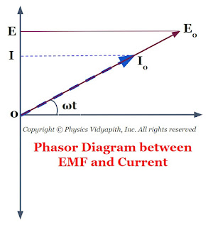
The phasor diagram between the EMF and current of resistance is also shown in the given figure below-
Phasor Diagram between EMF and Current

Mean Value and Root Mean Square Value of Alternating Current

Mean Or Average Value of Alternating Current:

Let us consider alternating current $i$ propagating in a circuit then the average value of current.

$ i_{mean}=\frac{1}{\left ( \frac{T}{2} \right )}\int_{0}^{\frac{T}{2}}i \:dt \qquad (1)$

$ where \quad i = i_{0}sin \omega t\quad(2)$

Now substitute the value of current $i$ in above equation $(1)$ 

$ i_{mean}= \frac{2}{T}\int_{0}^{\frac{T}{2}}i_0. sin \omega t.dt$

$ i_{mean}= \frac{2.i_{0}}{T}\int_{0}^{\frac{T}{2}}\sin \omega t.dt$

$ i_{mean}= \frac{2 i_{0}}{T}[\frac{-cos\:\omega t}{\omega} ]_{0}^{\frac{T}{2}}$

The value of $\omega$ is $\frac{2 \pi}{T}$ i.e $\omega=\frac{2\pi}{T}$

$ i_{mean}= \frac{2 i_{0}}{T \left (\frac{2\pi}{T} \right )}\left [ -cos \left (\frac{2 \pi}{T} \right ) \left ( \frac{T}{2} \right ) \\ \qquad \qquad \qquad +cos0^\circ \right ] $

$ i_{mean}= \frac{i_{0}}{\pi}\left [ - cos\pi+cos0^{\circ} \right ]$

$ i_{mean}=\frac{i_{0}}{\pi}\left [1+1 \right ]$

$ i_{mean} =\frac{2 i_{0}}{\pi}$

$ i_{mean} = 0.637\: i_{0}$

Thus, The mean (or average) value of alternating current for the cycle is $0.637$ times or $63.7 \%$ of the peak value.

Root mean square value of Alternating Current:

Let us consider current $i$ propagating in a circuit then the mean square value of alternating current.

$ \left (i_{mean} \right )^{2} = \frac{1}{T}\int_{0}^{T}i^{2}.dt \qquad(1)$

$ where\quad i= i_{0} \dot sin\omega t\qquad (2)$

Now substitute the value of current $i$ in above equation $(1)$

$ \left ( i_{mean} \right )^{2} = \frac{1}{T}\int_{0}^{T} \left ( i_{0} \:sin\omega t\right )^{2} dt $

$ \left (i_{mean} \right )^{2} = \frac{i_{0}^2}{T}\quad\int_{0}^{T} sin^{2}\omega t.dt$

$ \left (i_{mean} \right )^{2} = \frac{i_0^{2}}{T}\int_{0}^{T} \frac{1-cos2\omega t}{2}\ dt$

$ \left (i_{mean} \right )^{2} = \frac{i_o^{2}}{2T}\int_{0}^{T}\left ( 1-cos2\omega t \right )dt$

$ \left (i_{mean} \right )^{2} = \frac{i_{0}^{2}}{2T}\left [ \left ( t \right )_{0}^{T} - \left ( \frac{sin2 \omega t}{2 \omega} \right )_{0}^{T} \right ] $

$ \left (i_{mean} \right )^{2} = \frac{i_0^{2}}{2T}\left [ \left ( T-0 \right ) \\ \qquad\qquad\qquad -\frac{1}{2\omega}\left ( sin2\omega T-sin 0^{\circ} \right ) \right ]$

$ \left (i_{mean} \right )^{2} = \frac{i_0^{2}}{2T}\left [ \left ( T-0 \right ) \\ \qquad\qquad\qquad -\frac{1}{2\omega}\left ( sin2\omega T-sin0^{\circ} \right ) \right ]$

$ \left (i_{mean} \right )^{2} = \frac{i_0^{2}}{2T}\left [ T-\frac{1}{2\omega}\left ( sin4\pi \\ \qquad \qquad\qquad  -sin0^{\circ} \right ) \right ]$

$ \left (i_{mean} \right )^{2} = \frac{i_0^{2}}{2T}\left [ T-\frac{1}{2\omega}\left ( 0-0 \right ) \right ]$

$ \left ( i_{mean} \right )^{2}=\frac{i_0^{2}}{2}$

$ \left (i_{mean} \right )^{2} = \frac{i_0^{2}}{2}$

So root mean square value of above equation:

$ i_{rms} = \sqrt{i_{mean}^{2}}$

$i_{rms} = \frac{i_{0}}{\sqrt{2}}$

$i_{rms} = 0.707\:i_{0}$

Thus, the root mean square value of an alternating current is $0.707$ times or $70.7 \%$ of the peak value.

Popular Posts