Principle of Ruby Laser →
Ruby laser is the first working laser that was invented by T.H.Maima in 1960. It is a three-level solid-state pulsed laser that uses a synthetic ruby crystal or sapphire$(Al_{2}O_{3})$ as its gain medium and triply ionized chromium$(Cr^{+3})$ is used as a dopant.
Construction of Ruby Laser →
There are the following main components of ruby laser:
- Active Medium
- Resonant Cavity
- Pumping and Cooling Device
 |
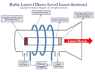
| Ruby laser diagram |
1. Active Medium →
The active medium or gained medium in ruby laser is a synthetic ruby crystal or Aluminium oxide $(Al_{2}O_{3})$ in the form of a cylindrical rod having size $2-30cm$ in length and $0.5-2.0cm$ in diameter. The size of the rod main varies depending upon the use. This gain medium falls in the category of 'narrow line width' laser material. A triply ionised chromium $(Cr^{+3})$ is used as doping material or dopant which works as an active ion. For doping of ruby $(Al_{2}O_{3})$, chromium oxide $(Cr_{2}O_{3})$ is mixed as impurity in ruby and small fraction of aluminium ion $(Al^{+3})$ in ruby are replaced by chromium ions $(Cr^{+3})$. The concentration of chromium ions $(Cr^{+3})$ is of the order of $0.055%$ and at this concentration, the number of chromium ions $(Cr^{+3})$ per cubic meter is nearly $10^{25}$. It is the chromium ions $(Cr^{+3})$ that population is set up in ruby laser and gives rise to the laser action. The chromium ions $(Cr^{+3})$ are active centers and provide the energy levels for both lasing transitions and pumping. The host Aluminium oxide $(Al_{2}O_{3})$ itself does not participate directly in lasing action.
2. Resonant Cavity →
The ends of the ruby are optically flat and parallel and then silvered, one end completely and the other only partially. The one end of the rod acts as fully reflecting and another one as partially reflecting. The reflectors can be plane-parallel or with a slight curvature, curved mirrors being more useful for compensating the thermal lensing of the rod which takes place during the pumping cycle. The space between the end faces is known as a resonant cavity in which light intensity can be built up or amplified by multiple reflections.
The ends of the ruby rod are polished with great precision, such that the ends are flat to within a quarter of a wavelength of the output light and parallel to each other within a few seconds of arc. The rod with its reflecting ends acts as a Fabry Perot resonator. Modern laser often uses rods with ends cut and polished at "Brewster's Angle" to eliminate the reflections from the ends of the rod.
3. Pumping and cooling Device →
In the ruby laser, population inversion is done by optical pumping. Xenon flash lamps provide the most efficient operation of ruby lasers with a pulse duration ranging from milliseconds. The ruby rod is wound by a helical xenon flashlight tube with an excitation source in the form of a power supply. The pumping absorption bands are at $4000 A^{\circ}$ and $5500 A^{\circ}$ with an approximation bandwidth of $500 A^{\circ}$ at each of the wavelengths. Pulses of energies up to $100J$ can be obtained through the pulse repetition rate is comparatively low, of the order of one to two pulses per second which limit the average power. Ruby laser requires high pumping flux to get population inversion due to which a considerable amount of heat is generated during laser operation. Ruby laser being highly temperature-dependent requires an arrangement of effective cooling. Water cooling of the rod combined with the higher thermal conductivity of Ruby provides a sufficient cooling effect to remove the excess heat. For this purpose, water is circulated in a glass tube surrounding the laser system. Being transparent in the wavelength region of pumping bands water does not affect the pumping flux from the flash lamp before it gets absorbed by Ruby road. Liquid nitrogen is also used as a coolant material in ruby lasers.
Working(Lasing Action) of Ruby Laser →
The energy level diagram of chromium ion in ruby is shown in the figure below:
 |
| The energy level diagram of chromium ion in ruby |
The energy level $E_{3}$ has two main pump bands or excited bands $T_{1}$ and $T_{2}$ having a bandwidth of nearly $800A^{\circ}$. The energy level $E_{2}$ which is known as the metastable state in ruby has a double energy level $A_{1}$ and $A_{2}$. These energy levels are separated by nearly $14A^{\circ}$. These are the twofold degenerate energy level.
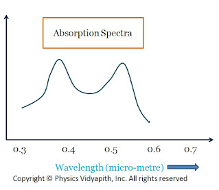
In the normal state, The chromium ions are in-ground energy state $E_{1}$. When light from the flash lamp is made to fall upon the ruby rod the incident radiation is absorbed by chromium ions and rises to an excited state $E_{3}$. The chromium ions in the ground state can absorb a photon of wavelength $5500A^{\circ}$ (green region) and jump to energy band $T_{2}$. It can also absorb the photon of a wavelength $4000A^{\circ}$ (Blue region) and jump to energy band $T_{1}$. The absorption spectrum of chromium ions is shown in the figure below
 |
| Absorption Spectra |
The chromium ion goes to upper energy state $T_{1}$and $T_{2}$ and stay for $10^{-8} sec $ and then make non radiative transition to metastable states $E_{1}$ and $E_{2}$ respectively which have very log life time $\approx10^{-3}sec$. The number of atoms in these states keeps increasing and at the same time number of atoms in the ground state $E_{1}$ goes on decreasing due to optical pumping. Thus the population inversion is achieved between the metastable state and ground state. At room temperature, if radiation is kept constantly, during the process of pumping, the population at $A_{2}$ level is almost $15%$ more than at level $A_{1}$. Some of the excited atoms in states $E_{3}$ return to ground state $E_{1}$ but with less probability.
When the population inversion is achieved light amplification starts in the resonant cavity. When excited atoms at metastable state $E_{2}$ make transition to ground level $E_{1}$ there are two weak lines at $6943 A^{\circ}$ ($A_{2}$ → $E_{1}$) and $6928 A^{\circ}$ ($A_{1}$ → $E_{1}$) each of width $\approx 6 A^{\circ}$. But Under the lasing condition, the line $6943 A^{\circ}$ dominates over $6928 A^{\circ}$. The emission spectrum of chromium ions in ruby is shown in the figure below:
 |
| Emission Spectra |
It shows that pumping transitions are spectrally broad while the emission transition is narrow. The wavelength of two spectral lines $6943 A^{\circ}$ and $6928 A^{\circ}$ are temperature dependent.


