Principle construction and working of potentiometer

Potentiometer- An ideal voltmeter that does not change the original potential difference, needs to have infinite resistance. But a voltmeter cannot be designed to have infinite resistance. The potentiometer is one such instrument that does not draw any current from the circuit and still measures the potential difference. so it behaves as an ideal voltmeter.

"A potentiometer is an instrument. This is used to measure the potential difference between two points of an electric circuit and emf of a cell."

Principle- The principle of the potentiometer depends upon the potential gradient along the wire i.e. "When a constant current flows in a wire then the potential drops per unit length of the wire".

Construction- A potentiometer consists of a long wire $AB$ of uniform cross-section, usually, this wire is $4 m$ to $10 m$ long and it is made of the material having high resistivity and low-temperature coefficient such as manganin or constant. Usually, $1m$ long-separate pieces of wire are fixed on a wooden board. These pieces of wires are parallel to each other and joined in series by thick copper strips. A meter scale is used to measure the position of the jockey on the wire and it is fixed parallel to the wire ( As shown in the figure). The ends $A$ and $B$ are connected to a strong battery, a plug key $(K)$, and a rheostat $(Rh)$. The circuit is called a driving or auxiliary circuit that sends a constant current $i$ through the wire $AB$. Thus the potential gradually drops from $A$ to $B$. This potential drop is measured with the help of a jockey and voltmeter. A jockey is used to make point contact on the wire and it slides on the wire along the length of the wire.
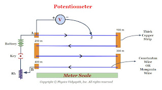
Diagram of Potentiometer
Working- When a constant current flow through a wire of uniform cross-section area and composition, the potential drop across any length of the wire is directly proportional to that length.

If the voltmeter is connected between the end $A$ and Jockey $j$, it reads the potential difference $V$ across the length of the wire $AJ$. So according to ohm's law-

$V=iR$

$V=i \rho \frac{l}{A} \qquad(1)$

for a wire $\rho,i,A$ are constants. So

$\frac{i \: l}{A}=K (Constant)$

Hence equation $(1)$ can be written as

$V=Kl$

$V \propto l$

Comments

Popular Posts

Numerical Aperture and Acceptance Angle of the Optical Fibre

Angle of Acceptance → If incident angle of light on the core for which the incident angle on the core-cladding interface equals the critical angle then incident angle of light on the core is called the "Angle of Acceptance. Transmission of light when the incident angle is equal to the acceptance angle If the incident angle is greater than the acceptance angle i.e. $\theta_{i}>\theta_{0}$ then the angle of incidence on the core-cladding interface will be less than the critical angle due to which part of the incident light is transmitted into cladding as shown in the figure below Transmission of light when the incident angle is greater than the acceptance angle If the incident angle is less than the acceptance angle i.e. $\theta_{i}<\theta_{0}$ then the angle of incidence on the core-cladding interface will be greater than the critical angle for which total internal reflection takes place inside the core. As shown in the figure below Transmission of lig

Fraunhofer diffraction due to a single slit

Let $S$ be a point monochromatic source of light of wavelength $\lambda$ placed at the focus of collimating lens $L_{1}$. The light beam is incident normally from $S$ on a narrow slit $AB$ of width $e$ and is diffracted from it. The diffracted beam is focused at the screen $XY$ by another converging lens $L_{2}$. The diffraction pattern having a central bright band followed by an alternative dark and bright band of decreasing intensity on both sides is obtained. Analytical Explanation: The light from the source $S$ is incident as a plane wavefront on the slit $AB$. According to Huygens's wave theory, every point in $AB$ sends out secondary waves in all directions. The undeviated ray from $AB$ is focused at $C$ on the screen by the lens $L_{2}$ while the rays diffracted through an angle $\theta$ are focussed at point $p$ on the screen. The rays from the ends $A$ and $B$ reach $C$ in the same phase and hence the intensity is maximum. Fraunhofer diffraction due to

Particle in one dimensional box (Infinite Potential Well)

Let us consider a particle of mass $m$ that is confined to one-dimensional region $0 \leq x \leq L$ or the particle is restricted to move along the $x$-axis between $x=0$ and $x=L$. Let the particle can move freely in either direction, between $x=0$ and $x=L$. The endpoints of the region behave as ideally reflecting barriers so that the particle can not leave the region. A potential energy function $V(x)$ for this situation is shown in the figure below. Particle in One-Dimensional Box(Infinite Potential Well) The potential energy inside the one -dimensional box can be represented as $\begin{Bmatrix} V(x)=0 &for \: 0\leq x \leq L \\ V(x)=\infty & for \: 0> x > L \\ \end{Bmatrix}$ $\frac{d^{2} \psi(x)}{d x^{2}}+\frac{2m}{\hbar^{2}}(E-V)\psi(x)=0 \qquad(1)$ If the particle is free in a one-dimensional box, Schrodinger's wave equation can be written as: $\frac{d^{2} \psi(x)}{d x^{2}}+\frac{2mE}{\hbar^{2}}\psi(x)=0$ $\frac{d^{2} \psi(x)}{d x