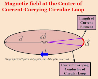
Mathematical Analysis of magnetic field at the center of circular loop:
Let us consider, a current-carrying circular loop of radius $a$ in which $i$ current is flowing. Now take a small length of a current element $dl$ so magnetic field at the center of a circular loop due to the length of current element $dl$. According to Biot-Savart Law:
$dB=\frac{\mu_{\circ}}{4 \pi} \frac{i .dl .sin\: \theta}{a^{2}} $
Here $\theta$ is the angle between length of current element $\left( \overrightarrow{dl} \right)$ and radius $\left( \overrightarrow{a} \right)$. These are perpendicular to each other i.e. $\theta = 90^{\circ}$
$dB=\frac{\mu_{\circ}}{4 \pi} \frac{i .dl .sin\: 90^{\circ}}{a^{2}} $
$dB=\frac{\mu_{\circ}}{4 \pi} \frac{i .dl }{a^{2}} \qquad \left(1 \right)$
The magnetic field at the center due to a complete circular loop
$B=\int dB \qquad \left(2 \right)$
From equation $(1)$ and equation $(2)$
$B=\int \frac{\mu_{\circ}}{4 \pi} \frac{i .dl}{a^{2}}$
$B=\frac{\mu_{\circ}}{4 \pi} \frac{i}{a^{2}} \int dl $
For complete loop $\int dl = 2 \pi a$, So from above equation that can be written as
$B=\frac{\mu_{\circ}}{4 \pi} \frac{i}{a^{2}} \left( 2 \pi a \right) $
$B=\frac{\mu_{\circ} i}{2 a}$
This is an equation of the magnetic field at the center of the circular loop.
Showing posts with label Magnetic Effect of Current. Show all posts
Showing posts with label Magnetic Effect of Current. Show all posts
Ampere's Circuital Law and its Modification
Ampere's Circuital Law Statement:
When the current flows in any infinite long straight conductor then the line integration of the magnetic field around the current-carrying conductor is always equal to the $\mu_{0}$ times of the current.
$\int \overrightarrow{B}. \overrightarrow{dl} = \mu_{\circ} i$
Derivation of Ampere's Circuital Law:
Let us consider, An infinite long straight conductor in which $i$ current is flowing, then the magnetic field at distance $a$ around the straight current carrying conductor
$B=\frac{\mu_{\circ}}{2 \pi} \frac{i}{a}$
Now the line integral of the magnetic field $B$ in a closed loop is
$\oint \overrightarrow{B}. \overrightarrow{dl} = \oint \frac{\mu_{\circ}}{2 \pi} \frac{i}{a} dl$
$\oint \overrightarrow{B}. \overrightarrow{dl} = \frac{\mu_{\circ}}{2 \pi} \frac{i}{a} \oint dl$
$\oint \overrightarrow{B}. \overrightarrow{dl} = \frac{\mu_{\circ}}{2 \pi} \frac{i}{a} \left(2 \pi a \right) \qquad \left( \because \oint dl= 2 \pi a \right)$
$\oint \overrightarrow{B}. \overrightarrow{dl} = \mu_{\circ}i$
Modified Ampere's circuital law:
When the capacitor is placed in between the conductors then a current flows in the capacitor which is known as displacement current $\left(i_{d} \right)$. So modified Ampere's circuital law:
$\oint \overrightarrow{B}. \overrightarrow{dl} = \mu_{\circ} \left( i + i_{d} \right)$
Force between two long and parallel current-carrying conductor
Derivation of Force between two long and parallel current-carrying conductors:
Let us consider:
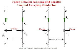
The two long straight, parallel conductors = $PQ$ and $RS$
The length of the conductor= $l$
The distance between the parallel conductor = $r$
The current flowing in conductor $PQ$ = $i_{1}$
The current flowing in conductor $RS$ = $i_{2}$
The magnetic field due to conductor $PQ$ = $B_{1}$
The magnetic field due to conductor $RS$ = $B_{2}$
The magnetic force on conductor $PQ$= $F_{1}$
The magnetic force on conductor $RS$= $F_{2}$
Now Consider the magnetic force on conductor $RS$ is i.e.
$F_{2}=i_{2}B_{1}l sin\theta$
Where $\theta$ is the angle between the magnetic field and length element of conductor i.e. $\theta=90^{\circ}$ so above equation can be written as,
$F_{2}=i_{2}B_{1}l sin 90^{\circ}$
$F_{2}=i_{2}B_{1}l \qquad(1)$
The magnetic field due to conductor PQ is:
$B_{1}= \frac{\mu_{\circ}}{2\pi} \frac{i_{1}}{r}$
Now substitute the value of $B_{1}$ in equation $(1)$ so the force on conductor $RS$
$F_{2}=\frac{\mu_{\circ}}{2\pi} \frac{i_{1}i_{2}}{r}l $
So the force per unit length on the conductor $RS$ is
$\frac{F_{2}}{l}=\frac{\mu_{\circ}}{2\pi} \frac{i_{1}i_{2}}{r} \qquad(2)$
Similarly, we can solve the force per unit length on the conductor $PQ$
$\frac{F_{1}}{l}=\frac{\mu_{\circ}}{2\pi} \frac{i_{1}i_{2}}{r} \qquad(3)$
So from the above equation, we can conclude that the force per unit length is the same on both conductors whether both have different amounts of current flowing. The generalized form of the force per unit length from the above equations is
$\frac{F}{l}=\frac{\mu_{\circ}}{2\pi} \frac{i_{1}i_{2}}{r}$
Note: When both parallel conductors have the same direction of current then the force between the conductor will be repulsive. or when both parallel conductors have opposite directions of current then the force between the conductor is attractive.
 |
| Force Between Parallel Current Carrying Conductor |
Force on current carrying conductor in uniform magnetic field
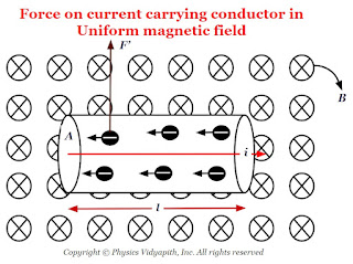
Derivation of force on current-carrying conductor in uniform magnetic field:
Let us consider:
The length of the conductor - $l$
The cross-section area of the current carrying conductor - $A$
The current flow in a conductor- $i$
The drift or average velocity of the free electrons - $v_{d}$
The current-carrying conductor is placed in a magnetic field - $B$
The total number of free electrons in the current carrying conductor - $N$
Now the magnetic force on one free electron in a conductor -
$F'= ev_{d}B sin\theta \qquad(1)$
The net force on the conductor is due to all the free electrons present in the conductor
$F=N\: F' \qquad(2)$
Let $N$ is the number of free electrons per unit volume of conductor. So the total number of free electrons in the $Al$ volume of the conductor will be
$N=nAl \qquad(3)$
Now substitute the value of $N$ and $F'$ from above equation $(1)$ and equation $(3)$ in equation $(2)$
$F=neAlv_{d}B\: sin\theta$
Where $i=neAv_{d}$
So from the above equation
$F=ilB \: sin\theta $
The Vector Form of the above equation:
$F=i \left(\overrightarrow{l} \times \overrightarrow{B} \right) $
Let us consider, a conductor of length of $l$ in which $i$ current carrying is flowing and placed in magnetic field $B$ at an angle $\theta$. If $i$ current is flowing in the conductor then magnetic force on the conductor depends upon
1) The magnetic force is directly proportional current.
$F \propto i \qquad(1)$
2.) The magnetic force is directly proportional to the length of the conductor.
$F \propto l \qquad(2)$
3.) The magnetic force is directly proportional to the magnetic field.
$F \propto B \qquad(3)$
4.) The magnetic force is directly proportional to the $sin \theta$. Here $\theta$ is the angle between the length of the current element and the magnetic field.
$F \propto sin \theta \qquad(4)$
from equation $(1)$, $(2)$, $(3)$, and equation $(4)$
$F \propto i \: l \: B sin\theta$
$F = k \: i \: l \: B sin\theta$
Here $k$ is constant which has value $1$, then above equation
$F = i\: l \: b \: sin\theta$
Vector form of the above equation:
$F = i \left( \overrightarrow{l} \times \overrightarrow{B} \right)$
 |
| Force on current carrying conductor in the uniform magnetic field |
Alternative Method
Principle, Construction and Working of Current Carrying Solenoid
Current Carrying Solenoid:
The Solenoid is an artificial magnet which is used for different purposes.
Principle of Solenoid:
The principle of the solenoid is based on the "Ampere Circuital Law" and its magnetic field is raised due to the current carrying a circular loop.
Construction of Solenoid:
The current carrying solenoid is consist of insulated cylindrical material and conducting wire. The conducting wire like copper is wrapped closely around the insulated cylindrical material ( like cardboard, clay, or plastic). The end faces of the conducting wire are connected to the battery.
Working:
When the electric current flow in the solenoid then a field (i.e. Magnetic field) is produced around and within the current carrying solenoid. This magnetic field is produced in solenoid due to circular loops of the solenoid and the direction of the magnetic field is depend upon the direction of the electric current flow in the circular loop. The magnetic field within the current carrying solenoid is uniform and parallel to the axis of the solenoid.
Derivation of the magnetic field due to long current carrying Solenoid:
Let us consider a very long current carrying solenoid of length $l$ in which $i$ electric current is flowing. Here its diameter is very less as compared to the length of the solenoid.
Now take a closed rectangular path $abcd$ in which the side $ab$ is parallel to the axis of the solenoid and sides $bc$ and $da$ are very long so that the side $cd$ is far from the solenoid and the magnetic field at this side is negligibly small.
Now apply Ampere's circuital law to the rectangular path $abcd$
$\oint \overrightarrow{B}. \overrightarrow{dl}=\mu_{\circ} i' \qquad(1)$
Where $i'$ is the current enclosed by the rectangle.
Let $n$ is the number of turns per unit length of the solenoid. So the number of turns in a length $x$ is = $nx$
The current in each turn is $i$ then the net current $(i')$ enclosed by the rectangle $abcd$ is $nxi$ i.e
$i'=nxi$
Now substitute the value of $i'$ in above equation $(1)$
$\oint \overrightarrow{B}. \overrightarrow{dl}=\mu_{\circ} nxi \qquad(2)$
Now expand the Ampere circuital law for closed rectangular $abcd$-
In above equation the term:
$\int_{b}^{c} \overrightarrow{B}.\overrightarrow{dl}= \int_{d}^{a} \overrightarrow{B}.\overrightarrow{dl}=0$
The above term is zero because along $bc$ and $da$ the magnetic field $\overrightarrow{B}$ and length element $\overrightarrow{dl}$ are perpendicular to each other.
$\int_{c}^{d} \overrightarrow{B}.\overrightarrow{dl}=0 $
The above term is zero because the magnetic field $\overrightarrow{B}$ outside the solenoid is negligible due long length of the solenoid.
The above equation $(3)$ can be written by applying the above condition-
$\oint \overrightarrow{B}.\overrightarrow{dl}=\int_{a}^{b} \overrightarrow{B}.\overrightarrow{dl}$
$\oint \overrightarrow{B}.\overrightarrow{dl}= \overrightarrow{B}\int_{a}^{b} \overrightarrow{dl}$
$\oint \overrightarrow{B}.\overrightarrow{dl}= B x \qquad(4)$
Where $x$- Length of $ab$
From equation $(2)$ and equation $(4)$, we get
$Bx=\mu_{\circ}nxl$
$B=\mu_{\circ}nl$
 |
| Long Current Carrying Solenoid |
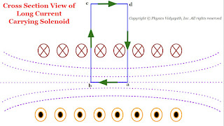 |
| Cross Section View of the long Current Carrying Solenoid |
$\oint \overrightarrow{B}.\overrightarrow{dl}=\int_{a}^{b} \overrightarrow{B}.\overrightarrow{dl}+ \int_{b}^{c} \overrightarrow{B}.\overrightarrow{dl} + \int_{c}^{d} \overrightarrow{B}.\overrightarrow{dl} + \int_{d}^{a} \overrightarrow{B}.\overrightarrow{dl} \qquad(3)$
Magnetic Field at the axis of a current-carrying Circular Loop
Derivation→
Let us consider, A circular loop which have radius $a$, carrying a current $i$. Let take a point $P$ on the axis of the loop at a distance $x$ from the center $O$ of the loop.
Now to find the magnetic field at point $P$, take a small current element of length $dl$ at the top of the loop. Let $r$ is the distance between the current element and point $P$. Now apply the Biot-Savart's Law to find the magnitude of the magnetic field due to small current-element $dl$ at point $P$ i.e.
$dB=\frac{\mu_{\circ}}{4 \pi} \frac{i \: dl\: sin\theta}{r^{2 }}$
Where $\theta$ is the angle between the length of the element $dl$ and the line joining the element to the point $P$. Here this angle is $90^{\circ}$
$dB=\frac{\mu_{\circ}}{4\pi} \frac{i \: dl}{r^{2}}\qquad(1)$
The direction of the magnetic field $d\overrightarrow{B}$ is in the plane of the paper and at right angles to the line $r$ as shown in the figure below (By applying the right-hand screw rule). It can be resolved into two components, one is vertical component of magnitude $dB\: sin\phi$ along the axis of the loop and the other is horizontal component of magnitude $dB\: cos\phi$ at right angles to the axis.
Let us consider another current element of the same length at the bottom of the loop, directly opposite to the first element, which is at right angles to the plane of the page but directed inwards. the field due to $d\overrightarrow{B}$ but directed as shown in the figure above. It is clear that components of both the fields at right angles to the axis are equal and opposite. Hence they cancel each other. The component along the axis are in the same direction and so they are added up.
If we imagine the whole of the loop to be divided into such current elements, the resultant field $\overrightarrow{B}$ at $P$ is directed along the axis and its magnitude is given by
$B=\int dB \: \sin\phi$
Now substitute the value of $dB$ from equation $(1)$
$B=\int \frac{\mu_{\circ}}{4\pi} \frac{i \: dl}{r^{2}} \: \sin\phi$
From figure, $sin\phi=\frac{a}{r}$, we get
$dB=\int \frac{\mu_{\circ}}{4 \pi} \frac{i}{r^{2}} \frac{a}{r}dl$
$dB=\int \frac{\mu_{\circ}}{4 \pi} \frac{ia}{r^{3}} dl$
$dB= \frac{\mu_{\circ}}{4 \pi} \frac{ia}{r^{3}} \int dl$
$dB= \frac{\mu_{\circ}}{4 \pi} \frac{ia}{r^{3}} 2 \pi \: a \qquad \left( \int dl = 2 \pi \: a \right)$
$dB= \frac{\mu_{\circ}ia^{2}}{2r^{3}}$
Agian from figure $r^{2}=\left( a^{2} + x^{2}\right)^{3}$ or $r= \left( a^{2} + x^{2}\right)^{3/2}$. Now substitute the value of $r$ in above equation.
$B=\frac{\mu_{\circ}\: i\: a^{2}}{2(a^{2}+x^{2})^{3/2}}$
If it is a coil of $N$ turns, then each turn will contribute equally to $B$. Thus
$B=\frac{\mu_{\circ}\: N \: i \: a^{2}}{2(a^{2}+x^{2})^{3/2}}$
The direction of the magnetic field $\overrightarrow{B}$ is along the axis of the loop and that of the coil.
Magnetic field at the Centre of the Loop→
At the centre of the coil, we have $x=0$
$B=\frac{\mu_{\circ}\: N \: i}{2a}$
Again the direction of the magnetic field $\overrightarrow{B}$ is perpendicular to the plane of the coil i.e. Along the axis of the coil.
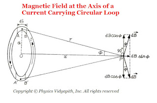 |
| Magnetic Field at the Axis of a Current-Carrying Circular Loop |
Magnetic Field due to a Straight Current-Carrying Conductor of Finite Length
Derivation→
Let us consider, a current-carrying conductor $XY$ having length $l$ in which current $i$ is flowing from $X$ to $Y$. Now, To find the magnetic field due to the conductor, take a point $P$ at a distance $d$ from point $O$ of the conductor.
Now consider a small length element $dl$ at the conductor which is making an angle $\theta$ from point $P$. The length element $dl$ is also making the angle $d\theta$ from point $O$. If $\theta_{1}$ and $\theta_{2}$ is the angle from point $O$ to point $X$ and $Y$ respectively. Than magnetic field at point $P$ due to small length element $dl$ which is at a distance $r$
$dB=\frac{\mu_{0}}{4\pi} \frac{i\: dl \: sin (90+\theta)}{r^{2}}$
$dB=\frac{\mu_{0}}{4\pi} \frac{i \: dl \: cos\theta}{r^{2}} \qquad(1)$
But from the figure, In $\Delta NOP$
$cos\theta=\frac{d}{r}$
$r=\frac{d}{cos\theta} \qquad(2)$
$tan\theta=\frac{l}{d}$
$l=d\:tan\theta$
Now differentiate the above equation with respect to $\theta$, then
$dl=d \: sec^{2}\theta \: d\theta \qquad(3)$
Now substitute the value of $dl$ and $r$ from equation$(2)$ and equation $(3)$ in equation$(1)$, then we get
$dB=\frac{\mu_{o}i}{4\pi}\frac{d \:sec^{2}\theta \: d\theta \: cos\theta}{\frac{d^{2}}{cos^{2}\theta}}$
$dB=\frac{\mu_{o}i}{4\pi}\frac{sec^{2}\theta \: d\theta \: cos^{3}\theta}{d}$
$dB=\frac{\mu_{o}i}{4\pi}\frac{cos\theta \: d\theta}{d} \qquad(4)$
The magnitude of the magnetic field $\overrightarrow{B}$ at point $P$ due to the whole conductor $XY$ is
$B=\int_{-\theta_{1}}^{\theta_{2}}dB$
Now substitute the value of $dB$ in above equation so
$B=\int_{-\theta_{1}}^{\theta_{2}} \frac{\mu_{o}i}{4\pi}\frac{cos\theta \: d\theta}{d} $
$B=\int_{-\theta_{1}}^{\theta_{2}} \frac{\mu_{o}i}{4\pi d}cos\theta d\theta $
$B= \frac{\mu_{o}i}{4\pi d} \left[ sin\theta\right] _{-\theta_{1}} ^{\theta_{2}} $
$B= \frac{\mu_{o}i}{4\pi d} \left[ sin(\theta _{2}) - sin(-\theta_{1})\right] $
$B=\frac{\mu_{o}i}{4\pi d}\left( sin\theta _{1} + sin\theta_{2}\right) $
Special Case→
The variation of the magnitude of magnetic field $B$ with distance $d$ is shown in the figure below→
The line of force of magnetic field $\overrightarrow{B}$ near a linear current-carrying conductor are concentric circles of varying radii with their centers at the conductor in a plane perpendicular to the conductor. The direction of the magnetic field $\overrightarrow{B}$ at a point $P$, distant $d$, will be along the tangent drawn on a circle of radius $d$ around the conductor.
 |
| Magnetic Field due to a Straight Current-Carrying Conductor of Finite Length |
- For a conductor of infinite length, i.e $\theta_{1}=\theta_{2}=90^{\circ}$ then magnetic field
$B=\frac{\mu_{0}}{4\pi} \frac{2i}{d} $$B=\frac{\mu_{0}}{2\pi} \frac{i}{d} $
- If the point $P$ is at a distance $d$ near one end of the conductor,i.e. $\theta_{1}=90^{\circ}$ and $\theta_{2}=0$ then magnetic field
$B=\frac{\mu_{0}}{4\pi} \frac{i}{d} $From the above equations, we can conclude that the magnetic field $B$ at point $P$ is proportional to the current $i$ and inversely proportional to the distance $d$ of point $P$ from the conductor.
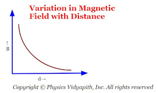 |
| Variation in Magnetic field with distance |
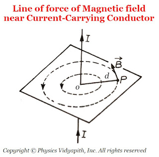 |
| Line of force of Magnetic field near Current-Carrying Conductor |
Motion of Charged Particles in Uniform Magnetic Field
Description:
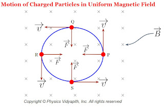
The motion of any particle is depends upon the force applying on it. In the magnetic field, the motion of charge is perpendicular to the magnetic force applied on the charge particle because of that the path of the charge particle becomes circular. If the direction of force and the direction of motion are not perpendicular to each other that is they are at any angle then the path of the charge particle becomes becomes helical.
A.) When $\overrightarrow{v}$ is perpendicular to $\overrightarrow{B}$→
Let us consider a charge $q$ enters in the magnetic field $\overrightarrow{B}$ from a point $O$ with velocity $\overrightarrow{v}$ directed perpendicular to the magnetic field $\overrightarrow{B}$.The general Expression for the force acting on the particle is
$\overrightarrow{F}=q(\overrightarrow{v} \times \overrightarrow{B})$
Here the magnetic field $\overrightarrow{B}$ is perpendicular to the plane of the page directed downwards which is shown in the figure below.
Since the velocity of charge particle $\overrightarrow{v}$ is perpendicular to the magnetic field $\overrightarrow{B}$ then the magnitude of the force $F$ will be
$F=qvB \qquad(1)$
Since the force is perpendicular to the velocity and the direction of velocity continuously changes but the magnitude of velocity is not changing. Therefore the particle will move in a circular path with constant speed in a uniform magnetic field and the magnetic force will act as a centripetal force. i.e.
$F=\frac{m v^{2}}{r} \qquad(2)$
Where
$r$ → Radius of the circular path
$m$ → mass of the particle
From equation $(1)$ and equation $(2)$
$\frac{m v^{2}}{r}=qvB$
$r=\frac{mv}{qB}$
The direction of the path of the particle depends upon the nature of the charge and the direction of the magnetic field.
The particle travels a distance $2\pi r$ in one revolution. So the time period of one revolution is
$T=\frac{2\pi r}{v} \qquad(3)$
Now substitute the value of $r=\frac{mv}{qB}$ in equation $(3)$ then we get
$T=\frac{2\pi m}{qB}$
The frequency of the particle $n=\frac{1}{T}$ can be written as
$n=\frac{qB}{2\pi m}$
From the above equations, We can conclude that the time period or frequency of the particle is independent of the speed $v$ of the particle. If the speed of the charge particle increases, its radius also increases so that the time taken to complete one cycle or revolution remains the same. If two identical charged particles enter the field with different speeds $v_{1}$ and $v_{2}$, then they move along the circle of smaller and larger radii respectively which is shown in the figure below.
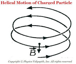
B.) When $\overrightarrow{v}$ is not perpendicular to $\overrightarrow{B}$→
Now, Again Let that the particle is entering with velocity $\overrightarrow{v}$ in the magnetic field $\overrightarrow{B}$, instead of being perpendicular to $\overrightarrow{B}$, makes angle $\theta (0 < \theta < 90^{\circ})$ with it. Now the velocity $\overrightarrow{v}$ may resolved into two components;
First is:
$v_{\parallel}=v \: cos\theta$ i.e. Parallel to magnetic field $\overrightarrow{B}$. This component gives the linear path to the particle.
Second is:
$v_{\perp}=v \: sin\theta$ i.e. Perpendicular to magnetic field $\overrightarrow{B}$. This component gives the circular path to the particle.
The resultant of these two-component gives the helical path to the particle whose axis is parallel to the magnetic field.
The radius of the circular path of the helix is
$r=\frac{mv_{\perp}}{qB}$
$r=\frac{mv \: sin\theta}{qB}$
The time period of the particle
$T=\frac{2\pi m}{qB}$
The linear distance traveled by the particle in the direction of the magnetic field in one complete circle is called the 'pitch $(p)$' of the path.
$p=v_{\parallel} \times T$
$T= v \: cos\theta \times \frac{2\pi m}{qB}$
Kinetic Energy of Charged Particle Moving in Uniform Magnetic Field→
The kinetic energy is
$K=\frac{1}{2}mv^{2}$
$K=\frac{(mv)^{2}}{2m}$
Now substitute the value of $mv$ from
$r=\frac{mv}{qB}$. Then we get
$K=\frac{1}{2}m \left( \frac{rqB}{m} \right)^{2}$
$K=\frac{r^{2}q^{2}B^{2}}{2m}$
$r$ → Radius of the circular path
$m$ → mass of the particle
 |
| The frequency and Time period of the particle are independent of the speed |
 |
| Helical Motion of Charged Particle |
Biot Savart's Law and Equation
Biot-Savart Law:
Biot-Savart law was discovered in 1820 by two physicists Jeans-Baptiste Biot and Felix Savart. According to this law:
$\qquad dB \propto \frac{i dl sin\theta}{r^{2}}$
Now replace the proportional sign with the constant i.e. $\frac{\mu_{0}}{4 \pi}$. Therefore the above given equation can be written as
$ dB = \frac{\mu_{0}}{4 \pi} \frac{i dl sin\theta}{r^{2}}$
The magnetic field at point $P$ due to entire conductor:-
$ B =\frac{\mu_{0}}{4 \pi} \int \frac{i dl sin\theta}{r^{2}}$
Case$(1)$: If $\theta=0^{\circ}$ then the magnetic field will be zero from the above equation i.e.
$B=0$
Case$(2)$: If $\theta=90^{\circ}$ then the magnetic field will be maximum from the above equation i.e.
$B =\frac{\mu_{0}}{4 \pi} \int \frac{i dl}{r^{2}}$.
The vector form of Biot-Savart magnetic field equation is:-
$ \overrightarrow{B} =\frac{\mu_{0} i}{4 \pi} \int \frac{ \overrightarrow{dl} \times \overrightarrow{r}}{r^{3}}$
- The magnetic field is directly proportional to the length of the current element.
$dB \propto dl \qquad (1)$
- The magnetic field is directly proportional to the current flowing in the conductor.
$dB \propto i \qquad (2)$
- The magnetic field is inversely proportional to the square of the distance between length of the current element $dl$ and point $P$ (This is that point where the magnetic field has to calculate).
$dB \propto \frac{1}{r^{2}} \qquad (3)$
- The magnetic field is directly proportional to the angle of sine. This angle is the angle between the length of the current element $dl$ and the line joining to the length of the current element $dl$ and point $P$.
$dB \propto sin\theta \qquad (4)$
Popular Posts
-
Let $S$ be a point monochromatic source of light of wavelength $\lambda$ placed at the focus of collimating lens $L_{1}$. The light beam is ...
-
Angle of Acceptance → "If incident angle of light on the core for which the incident angle on the core-cladding interface equals t...
-
Derivation of interference of light due to a wedge-shaped thin film: Interference of light due to wedge-shaped thin film The wedge...
-
Maxwell's Equations: Maxwell's equation of the electromagnetic wave is a collection of four equations i.e. Gauss's law of elec...
-
Let a plane wavefront be incident normally on slit $S_{1}$ and $S_{2}$ of equal $e$ and separated by an opaque distance $d$.The diffracted l...
Study-Material
Categories
Alternating Current Circuits
(10)
Atomic and Molecular Physics
(4)
Biomedical
(1)
Capacitors
(6)
Classical Mechanics
(12)
Current carrying loop in magnetic field
(5)
Current Electricity
(10)
Dielectric Materials
(1)
Electromagnetic Induction
(3)
Electromagnetic Wave Theory
(23)
Electrostatic
(22)
Energy Science and Engineering
(2)
Error and Measurement
(2)
Gravitation
(11)
Heat and Thermodynamics
(3)
Kinematics Theory Of Gases
(2)
Laser System & Application
(15)
Magnetic Effect of Current
(9)
Magnetic Substances
(3)
Mechanical Properties of Fluids
(5)
Nanoscience & Nanotechnology
(4)
Nuclear Physics
(7)
Numerical Problems and Solutions
(2)
Optical Fibre
(5)
Optics
(25)
Photoelectric Effect
(3)
Quantum Mechanics
(37)
Relativity
(8)
Semiconductors
(2)
Superconductors
(1)
Topic wise MCQ
(9)
Units and Dimensions
(1)
Waves
(5)
