The basic definition of Light:
Light is a form of energy that produces the sensation of vision in the eye by which we can see objects.
There are some facts about light as follows:
1. Lightwave moves along a straight line path.
2. Light waves can travel through both a vacuum and a medium.
3. Light is an electromagnetic wave.
4. Light waves are transverse waves in nature.
5. Light can be dispersed.
Besides these facts, light also shows the phenomenon of interference, diffraction, polarisation, photoelectric effect, etc.
To explain the above facts, many principles have been given from time to time, e.g., Newton's corpuscular theory, Huygen's wave theory, Maxwell's principle of electromagnetic waves, Planck's quantum principle, dual nature of light, etc.
Origin of Biomedical Signals
The biomedical signals differ from other signals only in terms of the application — signals that are used in the biomedical field. As such, biomedical signals are produced from a variety of sources. The following is a brief description of these sources:
1. Bioelectric signals: The bioelectric signal is unique to biomedical systems. It is produced by nerve cells and muscle cells. It is produced due to the membrane potential, which under certain conditions may be excited to generate an action potential. In single-cell measurements, the specific microelectrodes are used as sensors, and the action potential itself is considered as the biomedical signal. In more gross measurements, the surface electrodes are used as sensors, and the electric field generated by the action of many cells, distributed in the electrode’s vicinity, constitutes the bioelectric signal. Bioelectric signals are probably the foremost biosignals. The fact that most biosystems use excitable cells makes it possible, to use biosignals to study and monitor the main functions of the systems. The electric field propagates through the biological medium, and thus the potential may be acquired at relatively convenient locations on the surface, eliminating the need to invade the system. The bioelectric signal is acquired by a relatively simple transducer. A transducer is required in the field of biomedical because the electric conduction in the biomedical medium is executed through ions, while the conduction in the measurement system is executed through electrons. All these lead to the fact that the bioelectric signal is broadly used in most of the fields of biomedicine.
2. Bioimpedance signals: The impedance of the tissue contains important information related to its composition, blood volume, blood distribution, endocrine activity, autonomic nervous system activity, and many more. The bioimpedance signal is usually generated by injecting into the tissue under test sinusoidal currents (frequency range of $50 kHz–1 MHz$, with low current densities of the order of $20–20 mA$). The electrode polarization problems are minimized by choosing the frequency range and the low current densities are selected to prevent tissue damage mainly due to heating effects. Bioimpedance measurements are usually performed with four electrodes. Two electrodes (known as source electrodes) are used to inject the current into the tissue and these electrodes are connected to a current source. Remaining two electrodes (known as measuring electrodes) are placed on the tissue under investigation and used to measure the voltage drop generated by the current and the tissue impedance.
3. Bioacoustic signals: Many biomedical phenomena create acoustic noise. The measurement of this acoustic noise gives information about the underlying phenomenon. The flow of blood in the heart (i.e through the heart’s valves, or through blood vessels) generates typical acoustic noise. The flow of air through the upper and lower airways and in the lungs generates acoustic sounds. These sounds are called coughs, snores, and chest and lung sounds. These sounds are used extensively in medicine. Sounds are also produced in the digestive tract and in the joints. It also has been observed that the contracting muscle generates an acoustic noise or muscle noise. Since the acoustic energy propagates through the biological medium, the bioacoustic signal may be conveniently acquired on the surface, using acoustic transducers (microphones or accelerometers).
4. Biomagnetic signals: Many organs, such as the brain, heart, and lungs, produce extremely weak magnetic fields. The measurements of these fields provide information but are not included in other biosignals (such as bioelectric signals). Due to the low level of the magnetic fields to be measured, biomagnetic signals are usually of a very low signal-to-noise ratio. Extreme precautions must be taken in designing or developing the acquisition system of these signals.
5. Biomechanical signals: The term biomechanical signals includes all signals used in the biomedicine fields that originate from some mechanical function of the biological system. These signals include motion and displacement signals, pressure and tension signals, flow signals, and others. The measurement of bio-mechanical signals requires a variety of transducers, not always simple and inexpensive. The mechanical phenomenon does not propagate in biomedical signals, as do the electric, magnetic, and acoustic fields. Hence the measurement usually has to be performed at the exact site. This very frequently complex the measurement and forces it to be an invasive one.
6. Biochemical signals: The chemical measurements from the living tissue or from samples analyzed in the clinical laboratory produce biochemical signals. Measuring the concentration of various ions inside and around a cell using specific ion electrodes. It is an example of such a signal. Partial pressures of oxygen (pO2) and carbon dioxide (pCO2) in the blood or respiratory system are other examples. Biochemical signals are often very low-frequency signals. Mostly, biochemical signals are actually DC signals.
7. Biooptical signals: Bio-optical signals are the result of optical functions of the biological system, occurring naturally or induced by the measurement. Blood oxygenation may be analyzed by measuring the transmitted and backscattered light from a tissue ( i.e.in vivo and in vitro) in several wavelengths. Important information about the fetus may be acquired by measuring the fluorescence characteristics of the amniotic
fluid. Analysis of the Heart output may be performed by the dye dilution method, which requires the observation of the appearance of recirculated dye in the bloodstream. The development of fiberoptic technology has opened vast applications of bio-optical signals.
Principle Construction, Working and Angular Magnification of Compound Microscope
Principle: The principle of the compound microscope is based on the magnification of an image by using two lenses.
Construction: A compound microscope consists of two convergent lenses (i.e. objective lens $O$ and eye-piece lens $e$) placed coaxially in a double tube system. The objective lens is an achromatic convergent lens system of short focal length and short aperture. The other eye-piece lens $e$ is also an achromatic convergent lens system of large focal length and large aperture. The observation is taken through the eye-piece lens by the observer. The eye-piece lens is fitted outer side of a movable tube and the inner side connects with a non-movable tube in which the objective lens is fitted on another side of the non-movable tube. The separation between the objective or eye-piece lens can be changed by an arrangement, this is known as rack and pinion arrangement.
Working: Suppose a small object $ab$ is placed slightly away from the first focus $f_{\circ}$ of the objective lens which forms a real, inverted, and magnified image $a_{1}b_{1}$. Now adjust the eye-piece lens by moving like this, that the image $a_{1}b_{1}$ lies in between the optical center and the second focal length $f_{e}$ of the eye-piece lens. This image $a_{1}b_{1}$ works as an object for the eye-piece lens which forms a magnified, virtual, and final image $a_{2}b_{2}$. The final image $a_{2}b_{2}$ is generally formed at the least distance $D$ of distinct vision, although it can be formed anywhere between this position and infinity.
Angular Magnification Or Magnifying Power($M$):
The angular magnification or magnifying power can be defined as the ratio of the angle subtended by the image at the eye ($\beta$) to the angle subtended by the object at the eye when placed at least distance of distinct vision ($\alpha$)
$M= \frac{Angle \: subtended \: by \: the \: image \: at \: the \: eye \: (\beta)}{Angle \: subtended \: by \: the \: object \: at \: the \: eye \: when \\ placed \: at \: least \: distance \: of \: distinct \: vision \: (\alpha)}$
$M=\frac{\beta}{\alpha} \approx \frac{tan \beta}{tan \alpha} \quad (1)$
From figure
$tan \beta = \frac{a_{2}b_{2}}{a_{2} e} $
$tan \alpha = \frac{a_{2}a_{3}}{a_{2}e}$
Now subtitute these values in equation $(1)$, then
$M=\frac{\frac{a_{2}b_{2}}{a_{2} e}}{\frac{a_{2}a_{3}}{a_{2}e}}$
$M=\frac{a_{2}b_{2}}{a_{2}a_{3}}$
Here $a_{2}a_{3} = ab$
So the above equation can be written as
$M=\frac{a_{2}b_{2}}{ab}$
$M=\frac{a_{2}b_{2}}{ab} \frac{a_{1}b_{1}}{a_{1}b_{1}}$
$M=\frac{a_{2}b_{2}}{a_{1}b_{1}} \frac{a_{1}b_{1}}{ab}$
Here $m_{e}=\frac{a_{2}b_{2}}{a_{1}b_{1}}$ and $m_{\circ}= \frac{a_{1}b_{1}}{ab}$
Now substitute the values of $m_{e}$ and $m_{\circ}$ in the above equation
$M=m_{e} \times m_{\circ} \qquad(1)$
Where
$m_{e} \rightarrow$ The linear magnification produced by eye-piece lens system
$m_{\circ} \rightarrow$ The linear magnification produced by the object lens system
So now again from the figure
The linear magnification produced by object lens system $m_{\circ} = -\frac{v_{\circ}}{u_{\circ}}$
The linear magnification produced by eye-piece lens system $m_{e} = \frac{D}{u_{e}}$
Substitute the value of $m_{\circ}$ and $m_{e}$ in equation $(1)$
$M= -\frac{v_{\circ}}{u_{\circ}} \left( \frac{D}{u_{e}} \right) \qquad(2)$
Adjustment of a Compound Microscope:
1.) Adjustment for Clear Vision: In this final image an object is formed at least a distance of distinct vision $D$. For this configuration,
On substitution $u=-u_{e}$, $v=-D$ and $f=f_{e}$ in the lens formula for eyepiece lens
$\frac{1}{-D}+\frac{1}{u_{e}}=\frac{1}{f_{e}}$
$\frac{1}{u_{e}}=\frac{1}{f_{e}} + \frac{1}{D}$
$\frac{D}{u_{e}}= \left( \frac{D}{f_{e}} + 1 \right)$
Now substitute the value of $\frac{D}{u_{e}}$ in equation $(2)$
$M= -\frac{v_{\circ}}{u_{\circ}} \left(1+ \frac{D}{f_{e}} \right) $
The length of the microscope tube in this setup
$L=$ Distance between the object and the eye-piece lenses
$L= v_{\circ} + |u_{e}|$
2.) Adjustment for Relaxed Eye: In this configuration, the final image of an object is formed in a relaxed eye position i.e. at $\infty$. In this setup, the eye-piece lens system is moved back until the image of object $ab$, formed by object lens,i.e., $a_{1}b_{1}$ fall at (coincide with)second focus $f'_{e}$ of the eye-piece lens system. Mathematically this situation comes when $u_{e} = f_{e}$
Thus, the magnifying power in this position,
$M=-\frac{v_{\circ}}{u_{\circ}} \left( \frac{D}{f_{e}} \right)$
For this set the length of the microscope tube,
$L=v_{\circ}+f_{e}$
$m_{e} \rightarrow$ The linear magnification produced by eye-piece lens system
$m_{\circ} \rightarrow$ The linear magnification produced by the object lens system
Nanoparticles and Its Properties
Introduction:
The prefix 'nano' means a billionth ($10^{-9}$). The field of nanotechnology is the study of various structures of matter having dimensions of the order of a billionth of a meter. These particles are called nanoparticles. Nanotechnology is based on the fact that particles that are smaller than about $100 nm$ give rise to new properties of nanostructures built from them.
Particles that are smaller than the characteristic length for a particular phenomenon show different physical and chemical properties than particles of larger sizes. For example, mechanical properties, optical properties, conductivity, melting point, and reactivity have all been observed to change when particles become smaller than the characteristic length.
Gold and silver nanoparticles were used in window glass panes to obtain a variety of beautiful colors. Nanotechnology has a wide range of applications like producing lighter but stronger materials, constructing faster switches for computers, improving drug delivery to specific organs of the body, etc.
The radii of atoms and most of the molecules are less than a nanometer. Nanoparticles are generally considered to have a radius in the range of $1 nm$ to $100 nm$ which can have $25$ to $10^{6}$ atoms. A cluster of $1 nm$ radius has approximately $25$ atoms. This definition of nanoparticles based on size does not distinguish between molecules and nanoparticles as many organic molecules contain more than $25$ atoms.
Nanoparticles can be more appropriately defined as an aggregate of atoms, with a radius between 1 nm and 100 nm, with dimensions less than the characteristic length of some physical phenomena.
When particle size is less than the characteristic length of some physical phenomena, the particles show different properties. The nanoparticles show unique properties that change with their size. Classical mechanics is able to explain the properties of bulk materials but is unable to explain the properties of nanoparticles. Quantum mechanical principles have to be used to explain the properties of the nanoparticles.
Properties of Nanoparticles
As discussed earlier, the properties of nanoparticles are different from the bulk material. The properties of nanoparticles also vary with size and shape. Hence different properties can be obtained by changing the size and shape of the nanoparticles. Some of the properties of nanoparticles are as follows :
1) Optical properties: The color of nanoparticles is different from the bulk material. When a bulk material is reduced in size to a few hundred atoms, the energy band structure of the bulk material changes to a set of discrete energy levels. Atomic clusters of different sizes will have different energy level separations. As clusters of different sizes have different energy level separations, the color of the clusters (which are due to transitions between the energy levels) will depend on their size. Hence the size of the cluster can be altered to change the colour of a material. For example, gold in bulk form appears yellow but gold nanoparticles appear bright red in color. The medieval glass makers produced tinted glass with a beautiful variety of colors by dissolving metal particles like gold, silver, cobalt, iron, etc. Due to these metal nanoparticles, the glasses appear colored.
In semiconductor nanoparticles (which are used in quantum dots) there is a significant shift in the optical absorption spectra towards blue as the particle size is reduced.
2) Electrical properties: The resistivity in bulk matter is mainly due to the scattering of electrons by ions and crystal defects. In nanostructures, the resistivity mainly depends on scattering from the boundaries of nanoparticles when particle size becomes less than the mean free path between collisions. Thus smaller particle size increases the resistivity.
Various types of defects in the lattice also increase the resistivity by limiting the mean free path. However many nanostructures are too small to have internal defects.
Another effect of reduced size is the confinement of conduction electrons. In bulk conductors, the electrons move freely throughout the entire conductor. The situation changes when one or more dimensions of the conductor are made very small.
Consider a flat conducting plate with a large length and width but a small thickness in the range of a few nanometers. In this configuration, called a quantum well, the electron will be confined along one dimension but will move freely along the remaining two dimensions.
If a conducting wire has a long length but a very small diameter, the electrons can move freely along the length but will be confined in two mutually perpendicular transverse directions. This configuration is known as a quantum wire.
If all three dimensions of the conductor are in nanometer range, the configuration is called a quantum dot and the electron is confined in all three dimensions. Confinement of electrons to small dimensions leads to quantization of energy.
The level of doping in semiconductors gives rise to another important phenomenon. For typical doping levels of 1 donor impurity atom in $10^{8}$ atoms of semiconductor atoms, a quantum dot of $10^{7}$ semiconductor atoms would have an average of $10^{-1}$ electrons. In other words, on an average, one quantum dot in 10 will have a free electron. These result in the phenomena of single-electron tunneling and coulomb blockade. The conduction is due to the tunneling of electrons through the quantum dot. The electrons are blocked from tunneling except at discrete voltage change positions. This phenomenon is called coulomb blockade. The I-V characteristic shown in the above Figure is called the coulomb staircase.
3) Magnetic properties: Magnetic properties are basically due to the orbital and spin motions of electrons around the nucleus. Every electron in an atom has spin and orbital magnetic moment which, when added, gives the total magnetic moment of the electron. The vector sum of all the moments of electrons gives the total moment of the atom. In most of the atoms, the net magnetic moment is zero.
However, atoms like iron, cobalt, and manganese, have a net magnetic moment. Crystals of these become atoms ferromagnetic when magnetic moments of all atoms are aligned in the same direction. The magnetic moment of magnetic nanoparticles is observed to be less than the value for perfect alignment of all moments. The net magnetic moment is observed to decrease with increasing temperature. This is due to thermal vibration of atoms in the cluster which disturbs the alignment of magnetic moments.
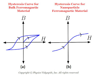
In bulk ferromagnetic materials, the magnetic moment is less than the moment the material would have if every atomic moment were aligned in the same direction. This is due to the presence of 'domains' which are regions in which all atomic moments are in one direction but moments of different domains are in different directions. When bulk ferromagnetic materials are subjected to alternating magnetic fields, they show hysteresis for which the B-H curve is shown in the above Figure (a). In nanosized ferromagnetic particles, essentially consisting of a single domain, there is no hysteresis and the $B-H$ curve is as shown in the above Figure (b). These particles are called the superparamagnetic.
The saturation magnetization is observed to increase significantly on decreasing the particle size. Another interesting property of nanoparticles is that clusters made of up nonmagnetic atoms like rhenium show magnetic moment which increases with the decrease in particle size.
4) Structural properties: The structure of small nanoparticles can be entirely different from that of the bulk material. The crystal structure of large nanoparticles is observed to be the same as the bulk material but with different lattice parameters. As a result of the changed structure, the electronic structure changes which in turn leads to changes in optical properties and reactivity. (TWD)
5) Mechanical properties: Mechanical properties like hardness, elasticity, and ductility depend upon the bonds between atoms. Imperfections in the crystal structure and impurities result in changes in these properties. As the nanoparticles are highly pure and free from imperfections, they show different mechanical properties than the bulk material. It has been observed that Young's modulus decreases in metallic nanocrystals with a decrease in particle size. The yield stress has been observed to increase with the decrease in grain size in bulk materials with nanosized grains. Hence stronger materials can be produced by making materials with nanosized grains. The carbon nanotubes are estimated to be about 20 times stronger than steel.
Difference Between Prism Spectra and Grating Spectra
Prism Spectra
1.) Prism spectra are obtained by the phenomena of dispersion of light.
2.) Prism spectra have only one order.
3.) A prism spectrum is of bright intensity.
4.) In prism spectra, spectral colors overlap each other.
5.) Red color is dispersed least whereas violet color disperses the maximum.
6.) Prism spectrum depends upon the material of prism.
7.) The prism spectral lines are curved.
.
Grating Spectra
1.) Grating spectra are obtained by the phenomena of diffraction of light.
2.) Grating spectra has more than one order.
3.) Grating spectra is of less intensity.
4.) In grating spectra, there is no overlapping of color.
5.) Red color diffracts the maximum whereas violet color diffracts the least.
6.) Grating spectra are independent of the material of grating.
7.) The grating spectral lines are almost straight.
Difference between interference and diffraction
Interference
1.) It is due to the superposition of two or more than two wavefronts coming from coherent sources.
2.) The intensity of all bright fringes are same
3.) Interference fringes either of the same size or decrease after moving away from the center.
4.) Dark fringes are usually perfectly dark.
5.) A minimum coherent source is needed.
Diffraction:
1.) It occurs due to secondary wavelets, originating from infinite different points of the same wavefronts.
2.) Central maxima of bright fringe is followed by either side maxima of decreasing intensity.
3.) Interference fringes are never of the same shape and size.
4.) Dark fringes are not perfectly dark.
5.) It is possible by either one or more than one source which need not be coherent.
Superconductors and its properties
Superconductivity
The property of a substance in which the electrical resistance of the substance is zero at very low temperatures. This property of substance is called superconductivity.
For certain substances, like mercury, the resistivity suddenly drops to zero at very low temperatures typically near the boiling point of liquid helium. Some metals, doped semiconductors, alloys and ceramics (i.e. these are insulators at room temperature and superconduct at higher temperatures than the metals) show superconductivity.
Temperature Dependence of Resistivity
In superconducting substances, the resistivity suddenly drops to zero at a particular temperature known as critical temperature ($T_{c}$) or
transition temperature and remains zero below that as shown in Figure below.
The critical temperature for mercury is $4.2 K$. Below this critical temperature, mercury is superconducting whereas above this temperature it behaves like a normal conductor. Different superconducting materials have different critical temperatures but the nature of the variation in resistivity with temperature remains more or less similar.
Properties of Superconductors
1.) Zero electrical resistance:
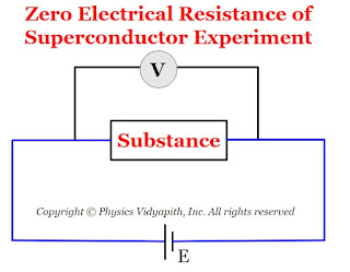
The electrical resistivity of superconductors is zero at very low temperatures. The experimental testing of zero resistance was tried by
connecting the substance at room temperature to a battery. A voltmeter was connected across the specimen to measure the electric potential difference across the specimen as shown in Figure below.
As the temperature of the substance gets lowered. It was observed that below a particular temperature (i.e. critical temperature), the electric potential difference across the substance suddenly dropped to zero.
2) Meissner effect:
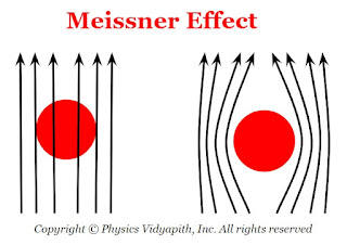
When a substance is placed in a weak magnetic field and cooled below the critical temperature then this substance behaves like perfect diamagnets with zero magnetic induction. This phenomenon is called the Meissner effect.
The magnetic induction inside the substance in the normal state is given by, Superconductors
$B = \mu_{\circ} (H +M)$
where $H$ is the externally applied magnetic field and $M$ is the magnetization inside the substance.
When the temperature $T$ of the specimen is lowered below its critical temperature
$B= 0$
$M_{\circ}(H + M) = 0$
$H = - M$
The susceptibility $\chi$ is given by,
$\chi=\frac{M}{H}$
For diamagnetic substance $\chi=-1$
As the relative permeability
$\mu_{r}=1+\chi$
$\therefore \mu_{r}=0$
This indicates perfect diamagnetism.
Meissner effect cannot be explained by assuming that the superconductor is a perfect conductor with zero electrical conductivity. The electric field is given by,
$E=\frac{V}{l}$
$E=\frac{iR}{l}$
$E=\frac{iR}{l} \frac{A}{A}$
$E=\frac{RA}{l} \frac{i}{A}$
$E=\rho J$
Where
$\rho$ = Resistivity
$J$= Current density
If $\rho$ becomes zero for a finite current density $J$, then $E =0$.
From Maxwell's equations,
$\nabla \times \overrightarrow{E} = \frac{d \overrightarrow{B}}{dt}$
As $E=0$, $\frac{d \overrightarrow{B}}{dt} =0$
$\therefore \overrightarrow{B} = Constant$
$\therefore$ In a conductor the flux cannot change on cooling below the critical temperature. This contradicts the Meissner effects according to which the flux must reduce to zero and hence superconductor is not just a perfect conductor.
Due to the Meissner effect, superconductors strongly repel external magnets which leads to magnetic levitation.
3) Effect of magnetic field on superconductors :
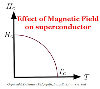
Superconductivity is destroyed by sufficiently strong magnetic fields. The minimum value of the applied magnetic field required to destroy
superconductivity is called the critical field $H_{c}$. and is a function of temperature. Above the critical temperature $T_{c}$, $H_{c} = 0$. Below the critical temperature, the variation of $H_{c}$, with temperature $T$ is as shown in Figure below and be represented by the equation
$H_{c}=H_{\circ} \left[ 1- \left(\frac{T}{T_{c}}\right) \right]$
where $H_{\circ}$ is the critical field at absolute zero.
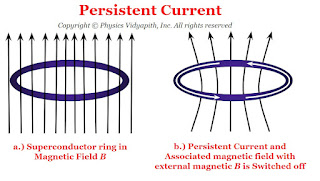
4) Persistent currents :
When a ring is placed in the magnetic field and the field is switched off, a current is induced in the ring. This induced current is called the persistent current.
The magnitude of current remains constant even though there is no source of e.m.f. as the resistance of the superconducting ring is zero. These currents flowing in the ring produce magnetic fields that do not require any power supply to maintain a constant field.
5) Isotope effect :
According to observations, the critical temperature of superconductors varies with isotopic mass. The critical temperature is smaller for larger isotopic mass. This phenomenon is called the isotope effect.
The relation between critical temperature $T_{c}$ and isotopic mass $M$ is given by,
$T_{c}M^{a} = Constant$
For most of the materials $a =\frac{1}{2}$
$\therefore T_{c}M^{\frac{1}{2}} = Constant$
$\therefore T_{c} \propto M^{-\frac{1}{2}} $
As lattice vibrations are reduced for larger isotopic masses, the isotope effect indicates that superconductivity is due to the interaction between electrons and lattice vibrations.
6) Critical Current:
All the current-carrying conductor produces a magnetic field around it. Similarly, When current flows through a superconducting wire, a magnetic field is produced around it. If the current in the superconducting wire is increased, the magnetic field intensity just outside it will increase and reach the critical field $H_{c}$. If the current is increased beyond this value, the wire will be subjected to a magnetic field exceeding the critical field due to which the superconducting state will be destroyed and then it will revert to its normal state. The maximum current that a superconductor can carry without reverting back to its normal state is known as critical current.
The magnetic induction due to a wire of radius $r$ just outside it is
$B=\frac{\mu_{\circ}i}{2 \pi r}$
$\mu_{\circ} H=\frac{\mu_{\circ}i}{2 \pi r}$
$H=\frac{i}{2 \pi r}$
If the critical current in $_{c}$, and critical field is $H_{c}$, ,
$H_{c}=\frac{i_{c}}{2 \pi r}$
$i_{c}=2 \pi r H_{c}$
Types of Superconductors
There are two types of superconductors based on the difference in magnetization exhibited by them. These are known as Type-I (or soft) and Type-II (or hard) superconductors.
1) Type-I Superconductors (Soft superconductors):
The magnetization curve for a Type-I -M superconductor is shown in Figure below. Type-I superconductors show the complete Meissner effect when the applied magnetic field H is less than the critical field $H_{c}$.
The magnetization in the superconductor is proportional to the applied field and the superconductors behave like perfect diamagnet.
For $H > H_{ç}$, the magnetization is negligible and the superconductor becomes a normal conductor. Pure elements show such magnetization curves. The values of $H_{c}$, are very low.
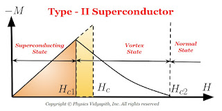
2) Type-II Superconductors (Hard superconductors)
The magnetization curve for a type-II superconductor is shown in Figure below.
There are two critical field $H_{c1}$ and $H_{c2}$ in Type-II superconductors that characterize it. Upto the lower critical field $H_{c1}$, the superconductor is perfectly diamagnetic and flux is completely ejected out from the superconductor. The magnetization in the superconductor is proportional to the applied field. Between $H_{c1}$ and $H_{c2}$, the Meissner effect is incomplete but electrically it is a superconductor but not magnetically. This state is called the mixed state or the vortex state.
The values of $H_{c}$ may be $100$ times or higher than the critical field $H_{c}$, for type-I superconductors.
Above the higher critical field $H_{c2}$ the superconductor becomes a normal conductor.
Type-II superconductors are usually alloys or transition metals with high values of electrical resistivity in the normal state.
High-Temperature Superconductors
Kamerlingh Onnes discovered superconductivity in mercury in 1911 with a critical temperature of $4.2 K$. The research was then focussed on materials with larger critical temperatures so that the phenomenon could become commercially viable.
But, till about 1986, the highest critical temperatures were observed to be nearly $20 K$. In 1986, an oxide of lanthanum, barium, and copper ($La_{1.85} Ba_{0.15} CuO_{4}$) was observed to have a critical temperature of $36 K$. In 1987, an oxide of yttrium, barium and copper ($YBa_{2}Cu_{3},0_{7}$) was found to have a critical temperature of $90 K$ and then an oxide of thallium, barium, calcium and copper($Tl_{2}Ba_{2}Ca_{2}Cu_{3}O_{10}$) was found to have a critical temperature of $120 K$.
The presence of parallel sheets of $CuO_{2}$ is the main feature of high-temperature superconductors.. Efforts are going on to find superconductors with critical temperatures near room temperature.
$J$= Current density
Kinetic Theory of Ideal Gases
German scientists R.Classius and J.C. Maxwell had propounded the kinetic theory of gases. According to this model, every gas is made up of very fine particles called molecules. All
the molecules of a gas are similar in all properties. We know that $ 1 cm^{3}$ of water is heated at $100^{\circ}C$ temperature, producing $1$ atmosphere pressure $1671 cm$ of water vapour. From this, it is known that the volume actually occupied by the molecules in $1671 cm^{3}$
of water vapour is only $1 cm^{3}$, and the remaining $1670 cm^{3}$ of volume is empty. In other words, in the gaseous state of matter, there is a lot of free space between the molecules. This fact is true for all gases. The molecules of gases are always moving randomly in all possible directions. During motion, these molecules collide with each other and with the walls of
the vessel in which the gas is kept. After each collision, both the direction and speed of motion of these molecules keep changing.
All collisions between molecules and molecules or between molecules and the walls are elastic. This implies that total kinetic energy and momentum are conserved.
Assumptions of Kinetic Theory of Gases
There are the following assumptions of the kinetic theory of gases.
1. The molecules of a gas are very small, rigid, spherical and completely elastic. The volume of the molecules is the volume in which the gas is present, is negligible compared to the volume of the gas.
2. Although the molecules of a gas can move with every possible velocity in every direction, but the number of molecules per unit volume or molecular density remains the same.
3. There is no force of attraction or repulsion between the molecules, as a result of which they do not have potential energy; their entire energy is kinetic energy.
4. When the molecules of a gas come very close to each other, there is a repulsive force between them, due to which their speed and direction of motion change.
This phenomenon is called a 'collision' between two molecules. Between two consecutive collisions, the molecules move in a straight line with a constant speed. The distance travelled by the molecule between two consecutive collisions is called the free path and its average is called the mean free path.
5. The mutual collision between the molecules and the collision between the molecule and the wall is perfectly elastic, that is, the kinetic energy of the molecules is conserved.
6 The time of collision between the molecules is negligible compared to the distance travelled freely by the molecule.
7. Since the amount of molecules is negligible and the velocity is high, therefore there is no effect of gravity on the motion of the molecules.
Newton's Corpuscular Model
Newton's Corpuscular Theory
In the year 1675, Newton proposed the corpuscular theory of light to explain the existing phenomenon of light. There are the following assumptions of this theory:
1. The light consists of very small, lightweight, and invisible particles. These particles are known as corpuscles.
2. These corpuscles move with the velocity of light in a homogeneous medium in all possible directions in a straight line and they carry kinetic energy with them.
3. When these corpuscles fall on the retina of the eye, they produce the sensation of vision.
4. The size of corpuscles of different colors is different (ie, the color of light depends on the size of the corpuscle).
(A) Success of Carpuscles Theory
Based on this theory, the following facts related to light were explained successfully:
1. The light has energy: Since corpuscles have kinetic energy. Therefore, the energy of the light beam is due to the kinetic energy of the corpuscles.
2. Motion of light along a straight line: Since velocity of the corpuscle is very high, the effect of external forces on it is
negligible. Therefore, it moves in a straight line.
3. Motion of light in vacuum: Corpuscles can move through vacuum.
4. Reflection of light: To explain the reflection of light, Newton assumed that when a corpuscle reaches close to a reflecting surface, then the surface repels it with a force whose direction is perpendicular to the surface and whose magnitude decreases sharply as the distance of corpuscles increases from the surface.
In Figure, let $PO$ be a reflecting surface and $P'Q'$ be an imaginary surface just above it at negligible height. When a light corpuscle moves towards the surface, then it moves along a straight line from $A$ to $B$ (since the force is zero). As it reaches the point $B$ of surface $PQ$, a repulsive force starts acting perpendicular to the surface (upward in the figure). Let $i$ is an angle of incidence at point $B$, then the velocity of the corpuscles at point $B$ has two components- component parallel to surface $V_{||} =v \: sin \: i$ and component perpendicular to surface $V_{|} = v \: cos \: i$. After crossing point $B$, the parallel component remains same but the perpendicular component decreases. At point $C$ of surface $PQ$, the perpendicular component becomes zero. After this direction of the perpendicular component changes and the corpuscles move along path CD. Beyond D again it moves along a straight line as the force becomes ineffective. If $r$ is the angle of reflection at point $D$, then the parallel component of velocity at $D$ will be $v\: sin\: r$. Since the parallel component remains constant. Therefore, comparing them at points $B$ and $D$.
$v \: sin \: i=v \: sin\: r$
$sin \: i= sin\: r$
$i=r$
i.e., the above equation shows that the incident angle and the reflected angle are equal. In the figure above, incident ray, reflected ray and normal all three are in the plane of paper. Therefore laws of reflection are verified.
5. Refraction of light: To explain the refraction of light, Newton considered two different situations :
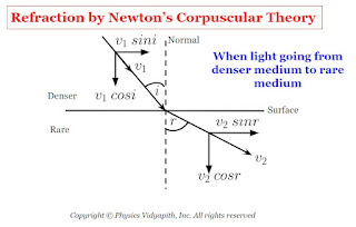
a.) When the light goes from a denser medium to a rare medium: In this condition when the corpuscle reaches near the surface, the surface exerts a normal repulsive force on it. As a result, the perpendicular component of velocity of the corpuscles decreases however it does not reduce to zero as in the case of refraction. Therefore, enters the second medium with a reduced perpendicular component and same constant value of the parallel component i.e., moves along a straight line bending away from normal.
If $i$ and $r$ are the angle of incidence and angle of refraction and $v_{1}$ and $v_{2}$ are the velocity of corpuscle in medium first and second medium. If the parallel component is constant,
$v_{1} \: sin \: i =v_{2} \: sin\: r$
$\frac{sin \: i}{sinr} =\frac{v_{2}}{v_{1}}$
From Figure
$i \lt r$
Therefore
$sin \: i \lt sin\: r$
$v_{2} \lt v_{1}$
Therefore, from the corpuscular theory, velocity light in a denser medium ($v_{1}$) is greater than the velocity light in a rare medium ($v_{2}$).
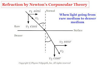
b.) When the light goes from a rare medium to a denser medium: In this condition when the corpuscle reaches near to the surface, the surface attracts it normally. As a result, the normal component of its velocity increases. Therefore, the corpuscular enters the second medium with an increased normal component and the same parallel component of velocity and moves along a straight line bending towards the normal.
$v_{1} \: sin \: i =v_{2} \: sin\: r$
$\frac{sin \: i}{sinr} =\frac{v_{2}}{v_{1}}$
From Figure
$i \gt r$
Therefore
$ sin \: i \gt sin\: r$
$v_{2} \gt v_{1}$
Therefore, velocity light in a denser medium ($v_{1}$) is greater than the velocity light in a rare medium ($v_{2}$).
B) Failure of the Corpuscles Theory
The following are the main reasons for the failure of this theory:
1. Interference, diffraction, polarisation of light, and the photoelectric effect, etc. can not be explained using this principle. For example, in interference, when two light beams interfere, darkness is produced at the same places. It is not possible that two corpuscles destroy each other.
2. According to this theory, the velocity of light is greater in the denser medium as compared to the rare medium. But Focault's had proved experimentally that the velocity of light is less in denser mediums as compared to the velocity of light in rare mediums.
3. According to this theory, greater the temperature of the source greater the velocity of the corpuscles. Actually, the velocity of light does not depend on the temperature of the source.
4. According to this theory, the mass of the source should decrease as it continuously emits corpuscles but it does not happen in reality.
5. In this theory two opposite assumptions are considered to explain reflection and refraction. To explain reflection and refraction through denser to rarer, the repulsive force by the surface is assumed and to explain refraction from rare to denser, the force of attraction by the surface is assumed. These assumptions are opposite and they don't have any scientific base.
Nuclear force and its properties
Nuclear Force
Properties of Nuclear Force
There are the following properties of nuclear force is given below.
(i) These are strong nuclear forces otherwise protons cannot exist in the nucleus.
(ii) The intensity of these forces is very large. The intensity of nuclear force is maximum among, so far known forces.
(iii) It is not electrical in nature. If we assume them electrical forces, then the protons cannot reside in nucleus.
(iv) These forces do not depend on charge. The force acting between the nucleons (such as proton-proton, neutron-neutron and proton-neutron) is of same nature.
(v) These are not gravitational forces because the mass of the particles inside the nucleus is very small, while the magnitude of nuclear force is very large.
(vi) These forces are short range forces. They are confined inside the nucleus (i. e., $10^{-15} m$ equal to the diameter of nucleus). There is no existence of these forces outside the nucleus.
A forces that act between the nucleons (i.e proton and neutron) inside the nucleus. This force is called the nuclear force.These forces are responsible to keep the nucleons bound inside the nucleus.
Popular Posts
-
Let $S$ be a point monochromatic source of light of wavelength $\lambda$ placed at the focus of collimating lens $L_{1}$. The light beam is ...
-
Angle of Acceptance → "If incident angle of light on the core for which the incident angle on the core-cladding interface equals t...
-
Derivation of interference of light due to a wedge-shaped thin film: Interference of light due to wedge-shaped thin film The wedge...
-
Maxwell's Equations: Maxwell's equation of the electromagnetic wave is a collection of four equations i.e. Gauss's law of elec...
-
Let a plane wavefront be incident normally on slit $S_{1}$ and $S_{2}$ of equal $e$ and separated by an opaque distance $d$.The diffracted l...
Study-Material
Categories
Alternating Current Circuits
(10)
Atomic and Molecular Physics
(4)
Biomedical
(1)
Capacitors
(6)
Classical Mechanics
(12)
Current carrying loop in magnetic field
(5)
Current Electricity
(10)
Dielectric Materials
(1)
Electromagnetic Induction
(3)
Electromagnetic Wave Theory
(23)
Electrostatic
(22)
Energy Science and Engineering
(2)
Error and Measurement
(2)
Gravitation
(11)
Heat and Thermodynamics
(3)
Kinematics Theory Of Gases
(2)
Laser System & Application
(15)
Magnetic Effect of Current
(9)
Magnetic Substances
(3)
Mechanical Properties of Fluids
(4)
Nanoscience & Nanotechnology
(4)
Nuclear Physics
(7)
Numerical Problems and Solutions
(2)
Optical Fibre
(5)
Optics
(25)
Photoelectric Effect
(3)
Quantum Mechanics
(34)
Relativity
(8)
Semiconductors
(2)
Superconductors
(1)
Topic wise MCQ
(9)
Units and Dimensions
(1)
Waves
(5)


