Physical Significance:
The physical significance of Maxwell's equations obtained from integral form are given below:
Maxwell's First Equation:
1. The total electric displacement through the surface enclosing a volume is equal to the total charge within the volume.
2. It represents Gauss Law.
3. This law is independent of time.
Charge acts as source or sink for the lines of electric force.
Maxwell's Second Equation:
1. The total magnetic flux emitting through any closed surface is zero. An isolated magnet do not exist monopoles.
2. There is no source or sink for lines of magnetic force.
3. This is time independent equation.
Maxwell's Third Equation:
1. The electromotive force around the closed path is equal to the time derivative of the magnetic displacement through any surface bounded by the path.
2. This gives relation between electric field $E$ and magnetic induction $B$.
3. This expression is time varying i.e. $E$ is generated by time variation of $B$.
4.This gives relation in variation of E with the time variation of $B$ or $H$.
5. This is a mathematical form of Faraday's law of electromagnetic induction or Lenz's
Law.
Maxwell's Fourth Equation:
1. The magneto-motive force around the closed path is equal to the conduction current
plus displacement current through any surface bounded by the path.
2. This is time dependent wave equation.
3 This is a mathematical form of Ampere circuital law.
4. Magnetic induction $B$ can be generated from $J$ and time variation of magnetic displacement $D$.
5. This relates the space variation of $B$ with time variation of $D$.
Circuit containing Inductor and Capacitor in Series (L-C Series Circuit )
Mathematical Analysis of L-C Series Circuit :
 Let us consider, a circuit containing inductor $L$ capacitor $C$ and these are connected in series. If an alternating voltage source is applied across it then the resultant voltage of the L-C circuit
$V=V_{L} - V_{C} \qquad(1)$
We know that:
$V_{L} = iX_{L}$
$V_{C} = iX_{C}$
So from equation $(1)$
$V= iX_{L} - iX_{C} $
$V=i \left(X_{L} - X_{C} \right) $
$\frac{V}{i}=\left(X_{L} - X_{C} \right) $
$Z=\left(X_{L} - X_{C} \right) \qquad(2)$
Where
$Z \rightarrow$ Impedance of L-C circuit.
$X_{L} \rightarrow$ Inductive Reactance which has value $\omega L$
$X_{C} \rightarrow$ Capacitive Reactance which has value $\frac{1}{\omega C}$
So from equation $(2)$, we get
$Z=\left( \omega L - \frac{1}{\omega C} \right) \qquad(3)$
The phase of resultant voltage:
 The phase of resultant voltage from current is $90^{\circ}$ as shown in the figure above.
The Impedance and Phase at Resonance Condition:($X_{L} = X_{C}$):
At resonance $X_{L} = X_{C} \qquad(5)$
$\omega L = \frac{1}{\omega C}$
$\omega^{2} = \frac{1}{L C}$
$\omega = \sqrt{\frac{1}{L C}}$
$2 \pi f = \sqrt{\frac{1}{L C}}$
$ f = \frac{1}{2 \pi}\sqrt{\frac{1}{L C}}$
Where $f \rightarrow$ Natural frequency of the circuit.
1.) The Impedance of the circuit at resonance condition:
Substitute the resonance condition i.e. $X_{L} = X_{C}$ in equation $(2)$ then the impedance of the L-C Circuit
$Z=0$
The impedance of the L-C circuit at resonance condition is zero.
2.) The Phase of resultant voltage at resonance condition:
There is not any change in the phase of resultant voltage at resonance condition i.e. that will be the same $90^{\circ}$.

$V_{C} = iX_{C}$
$Z \rightarrow$ Impedance of L-C circuit.
$X_{L} \rightarrow$ Inductive Reactance which has value $\omega L$
$X_{C} \rightarrow$ Capacitive Reactance which has value $\frac{1}{\omega C}$

Circuit containing Capacitor and Resistor in Series (C-R Series Circuit )
Mathematical Analysis of C-R Series Circuit :
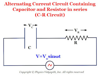 Let us consider, a circuit containing capacitor $C$ resistor $R$ and these are connected in series. If an alternating voltage source is applied across it then the resultant voltage of the C-R circuit
$V=\sqrt{ V_{C} ^{2} + V^{2}_{R}} \qquad(1)$
We know that:
$V_{R} = iR$
$V_{C} = iX_{C}$
So from equation $(1)$
$V=\sqrt{\left( iX_{C} \right)^{2} + \left(iR\right)^{2}} $
$V=i\sqrt{\left( X_{C} \right)^{2} + R^{2}} $
$\frac{V}{i}=\sqrt{\left( X_{C} \right)^{2} + R^{2}} $
$Z=\sqrt{\left( X_{C} \right)^{2} + R^{2}} \qquad(2)$
Where
$Z \rightarrow$ Impedance of C-R circuit.
$X_{C} \rightarrow$ Capacitive Reactance which has value $\frac{1}{\omega C}$
So from equation $(2)$, we get
$Z=\sqrt{\left( \frac{1}{\omega C} \right)^{2} + R^{2}} \qquad(3)$
The phase of resultant voltage:
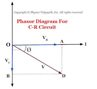 If the phase of resultant voltage from from current is $\phi$ then
$tan \phi = \frac{X_{C} }{R} \qquad(4)$
$tan \phi = \frac{\frac{1}{\omega C}}{R} $
$tan \phi = \frac{1}{\omega C R} $
$\phi = tan^{1} \left(\frac{1}{\omega C R}\right) $

$V_{C} = iX_{C}$
$Z \rightarrow$ Impedance of C-R circuit.
$X_{C} \rightarrow$ Capacitive Reactance which has value $\frac{1}{\omega C}$

Circuit containing Inductor and Resistor in Series (L-R Series Circuit )
Mathematical Analysis of L-R Series Circuit :
 Let us consider, a circuit containing inductor $L$ resistor $R$ and these are connected in series. If an alternating voltage source is applied across it then the resultant voltage of the L-R circuit
$V=\sqrt{ V_{L} ^{2} + V^{2}_{R}} \qquad(1)$
We know that:
$V_{R} = iR$
$V_{L} = iX_{L}$
So from equation $(1)$
$V=\sqrt{\left( iX_{L} \right)^{2} + \left(iR\right)^{2}} $
$V=i\sqrt{\left( X_{L} \right)^{2} + R^{2}} $
$\frac{V}{i}=\sqrt{\left( X_{L} \right)^{2} + R^{2}} $
$Z=\sqrt{\left( X_{L} \right)^{2} + R^{2}} \qquad(2)$
Where
$Z \rightarrow$ Impedance of L-R circuit.
$X_{L} \rightarrow$ Inductive Reactance which has value $\omega L$
So from equation $(2)$, we get
$Z=\sqrt{\left( \omega L \right)^{2} + R^{2}} \qquad(3)$
The phase of resultant voltage:
 If the phase of resultant voltage from from current is $\phi$ then
$tan \phi = \frac{X_{L} }{R} \qquad(4)$
$tan \phi = \frac{\omega L }{R} $
$\phi = tan^{1} \left(\frac{\omega L }{R}\right) $

$V_{L} = iX_{L}$
$Z \rightarrow$ Impedance of L-R circuit.
$X_{L} \rightarrow$ Inductive Reactance which has value $\omega L$

Circuit containing Inductor, Capacitor, and Resistor in Series (L-C-R Series Circuit )
Mathematical Analysis of L-C-R Series Circuit :
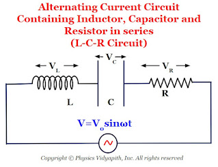 Let us consider, a circuit containing inductor $L$, capacitor $C$, and resistor $R$ and these are connected in series. If an alternating voltage source is applied across it then the resultant voltage of the L-C-R circuit
$V=\sqrt{\left( V_{L} -V_{C} \right)^{2} + V^{2}_{R}} \qquad(1)$
We know that:
$V_{R} = iR$
$V_{L} = iX_{L}$
$V_{C} = iX_{C}$
So from equation $(1)$
$V=\sqrt{\left( iX_{L} - iX_{C} \right)^{2} + (iR)^{2}} $
$V=i\sqrt{\left( X_{L} - X_{C} \right)^{2} + R^{2}} $
$\frac{V}{i}=\sqrt{\left( X_{L} - X_{C} \right)^{2} + R^{2}} $
$Z=\sqrt{\left( X_{L} - X_{C} \right)^{2} + R^{2}} \qquad(2)$
Where
$Z \rightarrow$ Impedance of L-C-R circuit.
$X_{L} \rightarrow$ Inductive Reactance which has value $\omega L$
$X_{C} \rightarrow$ Inductive Reactance which has value $\frac{1}{\omega C}$
So from equation $(2)$, we get
$Z=\sqrt{\left( \omega L - \frac{1}{\omega C} \right)^{2} + R^{2}} \qquad(3)$
The phase of resultant voltage:
 If the phase of resultant voltage from from current is $\phi$ then
$tan \phi = \frac{X_{L} - X_{C}}{R} \qquad(4)$
$tan \phi = \frac{\omega L - \frac{1}{\omega C}}{R} $
$ \phi = tan^{-1} \left( \frac{\omega L - \frac{1}{\omega C}}{R} \right) $
The Impedance and Phase at Resonance Condition:($X_{L} = X_{C}$):
At resonance $X_{L} = X_{C} \qquad(5)$
$\omega L = \frac{1}{\omega C}$
$\omega^{2} = \frac{1}{L C}$
$\omega = \sqrt{\frac{1}{L C}}$
$2 \pi f = \sqrt{\frac{1}{L C}}$
$ f = \frac{1}{2 \pi}\sqrt{\frac{1}{L C}}$
Where $f \rightarrow$ Natural frequency of the circuit
1.) The Impedance of the circuit at resonance condition:
Substitute the resonance condition i.e. $X_{L} = X_{C}$ in equation $(2)$ then the impedance of the L-C-R Circuit
$Z=R$
The impedance of the L-C-R circuit at resonance condition is equal to the resistance of the resistor applied in a circuit.
2.) The Phase of resultant voltage at resonance condition:
$tan\phi =0$
$tan\phi = tan 0^{\circ}$
$\phi=0^{\circ}$
The phase of resultant voltage at resonance condition is zero. i.e. the direction of resultant voltage in the direction of current in the circuit.
Note: There are following cases arise in the L-C-R circuit at resonance condition
Case -1:
If $X_{L} \gt X_{C}$, the $tan \phi$ is positive, i.e. $\phi$ is positive. In this case, the voltage leads to the current. Therefore, the circuit is more inductive rather than capacitive or resistive.
Case -2:
If $X_{L} \lt X_{C}$, the $tan \phi$ is negative, i.e. $\phi$ is negative. In this case, the voltage lags behind the current. Therefore, the circuit has a more capacitance-dominated circuit.
Case -3:
If $X_{L} = X_{C}$, the $tan \phi$ is zero, i.e. $\phi$ is negative. In this case, the voltage and the current are in phase. Therefore, the circuit is purely resistive.

$V_{L} = iX_{L}$
$V_{C} = iX_{C}$
$Z \rightarrow$ Impedance of L-C-R circuit.
$X_{L} \rightarrow$ Inductive Reactance which has value $\omega L$
$X_{C} \rightarrow$ Inductive Reactance which has value $\frac{1}{\omega C}$

Merits and Demerits of Alternating Current in Comparison to Direct Current
Merits and Demerits of AC in Comparison to DC
(a) Merits
(i) Alternating current can be increased or decreased by using a transformer.
This is the reason that Alternating current can be transmitted from one place to other place at relatively lower expenditure and minimum loss of energy. In Direct current, it is not possible.
(ii) Alternating current can be controlled by choke coil or capacitor at very small loss of energy. To control Direct current resistance is required in which energy loss is very high.
(ii) Alternating current can easily be converted into Direct current by using a rectifier but converting Direct current into Alternating current is not easy.
(iv) Alternating current is cheaper than DC. (life of a cell or battery is very limited).
(b) Demerits
(i) Alternating current is more dangerous as compared to Direct current.
(ii) Alternating current cannot be used in electrolysis.
(iii) Most of the Alternating current of high frequency flows on the surface of the wire, therefore, a thick wire by joining number of thin insulated wires in parallel are to be used.
Popular Posts
-
 Angle of Acceptance → "If incident angle of light on the core for which the incident angle on the core-cladding interface equals t...
 -
 Derivation→ Let us consider, The charge on a parallel-plate capacitor = $q$ The area of parallel-plate = $A$ The dis...
 -
Description: Unit of Energy The SI unit of energy is the Joule (J) , named after the English physicist James Prescott Joule. 1 Joule is...
-
 A.) Electric field intensity at different points in the field due to the uniformly charged solid conducting sphere: Let us consider, A s...
 -
 Principle: The principle of the compound microscope is based on the magnification of an image by using two lenses. Construction: A comp...
 -
 Derivation→ Let us consider, a current-carrying conductor $XY$ having length $l$ in which current $i$ is flowing from $X$ to $Y$. Now,...
 -
Principle of Ruby Laser → Ruby laser is the first working laser that was invented by T.H.Maima in 1960. It is a three-level solid-stat...
-
Gaussian Surface and its Properties: The Gaussian surface is a hypothetical or imaginary closed three-dimensional surface. This surface i...
-
Gauss's Law: Gauss's law for electric flux is given by Carl Friedrich Gauss in 1813. He extended the work of Joseph-Louis Lagr...
-
 Derivation → Capacitance of an Isolated Spherical Conductor Let us consider an isolated spherical conductor of radius $a$ is placed i...

