Magnetic potential energy:
When a current carrying loop is placed in an external magnetic field the torque is acted upon the current loop which tends to rotate the current loop in a magnetic field. Therefore the work is done to change the orientation of the current loop against the torque. This work is stored in the form of magnetic potential energy in the current loop. This is known as the magnetic potential energy of the current loop.
Note: The current loop has magnetic potential energy depending upon its orientation in the magnetic field.
Derivation of Potential energy of current-loop in a magnetic field:
Let us consider, A current loop of magnetic moment $\overrightarrow{m}$ is held with its axis at an angle $\theta$ with the direction of a uniform magnetic field $\overrightarrow{B}$. The magnitude of the torque acting on the current loop or magnetic dipole is
$\tau=m \: B \: sin\theta \qquad(1)$
Now, the current loop is rotated through an infinitesimally small angle $d\theta$ against the torque. The work done to rotate the current loop
$dW=\tau \: d\theta$
$dW=m \: B \: sin\theta \: d\theta $ {from equation $(1)$}
If the current loop is rotated from an angle (or orientation) $\theta_{1}$ to $\theta_{2}$ then the work done
$W=\int_{\theta_{1}}^{\theta_{2}} m \: B \: sin\theta d\theta$
$W= m \: B \: \left[ -cos\theta \right]_{\theta_{1}}^{\theta_{2}} $
$W= m \: B \: \left( cos\theta_{1} - cos\theta_{2} \right) $
This work is stored in the form of potential energy $U$ of the current loop :
$U= m \: B \: \left( cos\theta_{1} - cos\theta_{2} \right) $
If $\theta_{1}=90^{\circ}$ and $\theta_{2}= \theta$
$U= m \: B \: \left( cos90^{\circ} - cos\theta \right) $
$U= - m \: B \: cos\theta $
$U= - \overrightarrow{m} . \overrightarrow{B}$
Thus, a current loop has minimum potential energy when $\overrightarrow{m}$ and $\overrightarrow{B}$ are parallel and maximum potential energy when $\overrightarrow{m}$ and $\overrightarrow{B}$ are antiparallel.
Magnetic Dipole Moment of Current carrying loop
Current carrying Loop or Coil or Solenoid:
The current carrying loop (or Coil or solenoid) behaves like a bar magnet. A bar magnet with the north and south poles at its ends is a magnetic dipole, so a current -loop is also a magnetic dipole.
Equation of Magnetic Dipole Moment of Current carrying Loop:
When a current loop is suspended in a magnetic field, it experiences the torque which tends to rotate the current loop to a position in which the axis of the loop is parallel to the field. So the magnitude of the torque acting on the current loop in the uniform magnetic field $\overrightarrow{B}$ is given by:
$\tau=iAB sin\theta \qquad(1)$
Where $A$ - Area of the current loop
We also know that when the electric dipole is placed in the electric field, it also experiences the torque which tends to rotate the electric dipole in the electric field. So the magnitude of the torque on the electric dipole in the uniform electric field $\overrightarrow{E}$ is given by:
$\tau=pE sin\theta \qquad(2)$
Where $p$ - The magnitude of the electric dipole moment
Now compare the equation $(1)$ and equation $(2)$ and we can conclude that the current loop also has a magnetic dipole moment just like an electric dipole have an electric dipole moment. The magnetic dipole moment is associated with the current in the loop and the area of the current loop. It is represented by $\overrightarrow {m}$. So the magnitude of the magnetic dipole moment of current carrying loop is:
$m=iA$
The vector form of the magnetic dipole moment current carrying loop is
$\overrightarrow{m} = i\overrightarrow{A}$
The magnetic dipole moment of current carrying coil:
If the current-carrying loop has $N$ number of turns (i.e current carrying coil) then the magnetic dipole moment of current carrying coil:
$m=NiA$
The vector form of the magnetic dipole moment of the current carrying coil is
$\overrightarrow{m} =N i\overrightarrow{A}$
The magnetic dipole moment of Circular Loop:
Let us consider the circular loop of radius $a$ in which current $i$ is flowing the magnitude of the magnetic dipole moment of the circular loop:
$m=i A$
Here the area $A$ of the circular loop is $\pi a^{2}$ then the magnitude of the magnetic dipole moment of the circular loop is:
$m=i \pi a^{2} \qquad(3)$
The magnetic field at the center of the current carrying a circular loop in terms of current is:
$B=\frac{\mu_{\circ}i}{2a}$
Now substitute the value of $i$ from equation $(3)$ in the above equation then the magnetic field at the center of the current carrying circular loop in terms of magnetic dipole moment is:
$B=\frac{\mu_{\circ}m}{2\pi a^{3}}$
$B=\frac{\mu_{\circ}}{4\pi} \frac{2m}{a^{3}}$
Force between two long and parallel current-carrying conductor
Derivation of Force between two long and parallel current-carrying conductors:
Let us consider:
The two long straight, parallel conductors = $PQ$ and $RS$
The length of the conductor= $l$
The distance between the parallel conductor = $r$
The current flowing in conductor $PQ$ = $i_{1}$
The current flowing in conductor $RS$ = $i_{2}$
The magnetic field due to conductor $PQ$ = $B_{1}$
The magnetic field due to conductor $RS$ = $B_{2}$
The magnetic force on conductor $PQ$= $F_{1}$
The magnetic force on conductor $RS$= $F_{2}$
Now Consider the magnetic force on conductor $RS$ is i.e.
$F_{2}=i_{2}B_{1}l sin\theta$
Where $\theta$ is the angle between the magnetic field and length element of conductor i.e. $\theta=90^{\circ}$ so above equation can be written as,
$F_{2}=i_{2}B_{1}l sin 90^{\circ}$
$F_{2}=i_{2}B_{1}l \qquad(1)$
The magnetic field due to conductor PQ is:
$B_{1}= \frac{\mu_{\circ}}{2\pi} \frac{i_{1}}{r}$
Now substitute the value of $B_{1}$ in equation $(1)$ so the force on conductor $RS$
$F_{2}=\frac{\mu_{\circ}}{2\pi} \frac{i_{1}i_{2}}{r}l $
So the force per unit length on the conductor $RS$ is
$\frac{F_{2}}{l}=\frac{\mu_{\circ}}{2\pi} \frac{i_{1}i_{2}}{r} \qquad(2)$
Similarly, we can solve the force per unit length on the conductor $PQ$
$\frac{F_{1}}{l}=\frac{\mu_{\circ}}{2\pi} \frac{i_{1}i_{2}}{r} \qquad(3)$
So from the above equation, we can conclude that the force per unit length is the same on both conductors whether both have different amounts of current flowing. The generalized form of the force per unit length from the above equations is
$\frac{F}{l}=\frac{\mu_{\circ}}{2\pi} \frac{i_{1}i_{2}}{r}$
Note: When both parallel conductors have the same direction of current then the force between the conductor will be repulsive. or when both parallel conductors have opposite directions of current then the force between the conductor is attractive.
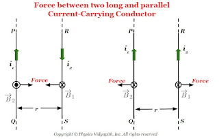 |
| Force Between Parallel Current Carrying Conductor |
Force on current carrying conductor in uniform magnetic field
Derivation of force on current-carrying conductor in uniform magnetic field:
Let us consider:
The length of the conductor - $l$
The cross-section area of the current carrying conductor - $A$
The current flow in a conductor- $i$
The drift or average velocity of the free electrons - $v_{d}$
The current-carrying conductor is placed in a magnetic field - $B$
The total number of free electrons in the current carrying conductor - $N$
Now the magnetic force on one free electron in a conductor -
$F'= ev_{d}B sin\theta \qquad(1)$
The net force on the conductor is due to all the free electrons present in the conductor
$F=N\: F' \qquad(2)$
Let $N$ is the number of free electrons per unit volume of conductor. So the total number of free electrons in the $Al$ volume of the conductor will be
$N=nAl \qquad(3)$
Now substitute the value of $N$ and $F'$ from above equation $(1)$ and equation $(3)$ in equation $(2)$
$F=neAlv_{d}B\: sin\theta$
Where $i=neAv_{d}$
So from the above equation
$F=ilB \: sin\theta $
The Vector Form of the above equation:
$F=i \left(\overrightarrow{l} \times \overrightarrow{B} \right) $
Let us consider, a conductor of length of $l$ in which $i$ current carrying is flowing and placed in magnetic field $B$ at an angle $\theta$. If $i$ current is flowing in the conductor then magnetic force on the conductor depends upon
1) The magnetic force is directly proportional current.
$F \propto i \qquad(1)$
2.) The magnetic force is directly proportional to the length of the conductor.
$F \propto l \qquad(2)$
3.) The magnetic force is directly proportional to the magnetic field.
$F \propto B \qquad(3)$
4.) The magnetic force is directly proportional to the $sin \theta$. Here $\theta$ is the angle between the length of the current element and the magnetic field.
$F \propto sin \theta \qquad(4)$
from equation $(1)$, $(2)$, $(3)$, and equation $(4)$
$F \propto i \: l \: B sin\theta$
$F = k \: i \: l \: B sin\theta$
Here $k$ is constant which has value $1$, then above equation
$F = i\: l \: b \: sin\theta$
Vector form of the above equation:
$F = i \left( \overrightarrow{l} \times \overrightarrow{B} \right)$
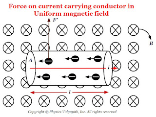 |
| Force on current carrying conductor in the uniform magnetic field |
Alternative Method
Principle, Construction and Working of Current Carrying Solenoid
Current Carrying Solenoid:
The Solenoid is an artificial magnet which is used for different purposes.
Principle of Solenoid:
The principle of the solenoid is based on the "Ampere Circuital Law" and its magnetic field is raised due to the current carrying a circular loop.
Construction of Solenoid:
The current carrying solenoid is consist of insulated cylindrical material and conducting wire. The conducting wire like copper is wrapped closely around the insulated cylindrical material ( like cardboard, clay, or plastic). The end faces of the conducting wire are connected to the battery.
Working:
When the electric current flow in the solenoid then a field (i.e. Magnetic field) is produced around and within the current carrying solenoid. This magnetic field is produced in solenoid due to circular loops of the solenoid and the direction of the magnetic field is depend upon the direction of the electric current flow in the circular loop. The magnetic field within the current carrying solenoid is uniform and parallel to the axis of the solenoid.
Derivation of the magnetic field due to long current carrying Solenoid:
Let us consider a very long current carrying solenoid of length $l$ in which $i$ electric current is flowing. Here its diameter is very less as compared to the length of the solenoid.
Now take a closed rectangular path $abcd$ in which the side $ab$ is parallel to the axis of the solenoid and sides $bc$ and $da$ are very long so that the side $cd$ is far from the solenoid and the magnetic field at this side is negligibly small.
Now apply Ampere's circuital law to the rectangular path $abcd$
$\oint \overrightarrow{B}. \overrightarrow{dl}=\mu_{\circ} i' \qquad(1)$
Where $i'$ is the current enclosed by the rectangle.
Let $n$ is the number of turns per unit length of the solenoid. So the number of turns in a length $x$ is = $nx$
The current in each turn is $i$ then the net current $(i')$ enclosed by the rectangle $abcd$ is $nxi$ i.e
$i'=nxi$
Now substitute the value of $i'$ in above equation $(1)$
$\oint \overrightarrow{B}. \overrightarrow{dl}=\mu_{\circ} nxi \qquad(2)$
Now expand the Ampere circuital law for closed rectangular $abcd$-
In above equation the term:
$\int_{b}^{c} \overrightarrow{B}.\overrightarrow{dl}= \int_{d}^{a} \overrightarrow{B}.\overrightarrow{dl}=0$
The above term is zero because along $bc$ and $da$ the magnetic field $\overrightarrow{B}$ and length element $\overrightarrow{dl}$ are perpendicular to each other.
$\int_{c}^{d} \overrightarrow{B}.\overrightarrow{dl}=0 $
The above term is zero because the magnetic field $\overrightarrow{B}$ outside the solenoid is negligible due long length of the solenoid.
The above equation $(3)$ can be written by applying the above condition-
$\oint \overrightarrow{B}.\overrightarrow{dl}=\int_{a}^{b} \overrightarrow{B}.\overrightarrow{dl}$
$\oint \overrightarrow{B}.\overrightarrow{dl}= \overrightarrow{B}\int_{a}^{b} \overrightarrow{dl}$
$\oint \overrightarrow{B}.\overrightarrow{dl}= B x \qquad(4)$
Where $x$- Length of $ab$
From equation $(2)$ and equation $(4)$, we get
$Bx=\mu_{\circ}nxl$
$B=\mu_{\circ}nl$
 |
| Long Current Carrying Solenoid |
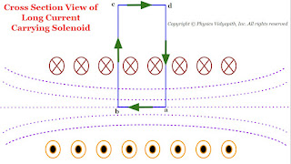 |
| Cross Section View of the long Current Carrying Solenoid |
$\oint \overrightarrow{B}.\overrightarrow{dl}=\int_{a}^{b} \overrightarrow{B}.\overrightarrow{dl}+ \int_{b}^{c} \overrightarrow{B}.\overrightarrow{dl} + \int_{c}^{d} \overrightarrow{B}.\overrightarrow{dl} + \int_{d}^{a} \overrightarrow{B}.\overrightarrow{dl} \qquad(3)$
Comparison of Step Index and Graded Index Fibres
Comparison of Step Index Fibres and Graded Index Fibres(GRIN)→
| S.No. | Step Index Fibre | Graded Index Fibre |
|---|---|---|
| 1. | In a step-index fibre, the refractive index of the core a constant value. | In graded-index fibre, the refractive index in the core decreases continuously in a nearly parabolic manner from a maximum value at the centre of the core to a constant value at the core-cladding interface. |
| 2. |
For a step-index fibre, the variation of refractive index is mathematically expressed as,
$\begin{cases} & \mu(r)=\mu_{1} \qquad 0 < r < a \quad for (core)\\ & \mu(r)=\mu_{2} \qquad r >a \quad for(Cladding)\\ \end{cases} \\ Where \: \mu_{1} > \mu{2} $ |
Parabolic refractive index variation in GRIN fibre is mathematically expressed as,
$ \begin{cases} & \mu^{2}(r)=\mu^{2}_{1} \left[ 1- \left(\frac{r}{\alpha} \right)^{2} \right] \qquad 0 < r < a \quad for (core) \\ & \mu(r)=\mu^{2}_{2} \qquad \qquad \qquad \qquad r > a \quad for (Cladding) \end{cases} $ |
| 3. | In the step-index fibre, the propagating light rays reflect abruptly from the Core cladding boundary. | In graded-index fibre, the propagating light rays bend smoothly as they approach the cladding. |
| 4. | for given fibre diameter, the numerical aperture of step-index fibre is large. | For the same fibre diameter, the numerical aperture of graded-index fibre is small. |
| 5. | In the step-index fibre, there may be some irregularities at the interface between the core and cladding. | In the graded-index fibre, there are no such irregularities at the interface between core and cladding. |
| 6. | The step-index fibre has higher attenuation. | The graded-index fibre has lower attenuation. |
| 7. | For a step-index fibre of a given physical size, with a loss of power of the order of $12 \frac{dB}{km}$, the numerical aperture is of the order of $0.2$ to $0.35$. | For a graded-index fibre of the same physical size, with an attenuation between $5$ to $10 \frac{dB}{km}$, the numerical aperture tends to run between $0.16$ and $0.2$ |
| 8. |
In step index fibre, the time interval at the output end or pulse dispersion is expressed as,
$\Delta \tau = \frac{\mu_{1} l}{c} \left ( \frac{\mu_{1}}{\mu_{2}} - 1 \right)=\frac{\mu_{1} l}{c} \Delta$ Where $l$ → The length of the fibre. |
In a graded index fibre, the time interval at the output end or pulse dispersion is expressed as,
$\Delta \tau = \frac{\mu_{2} l}{2c} \left ( \frac{\mu_{1} - \mu_{2}} {\mu_{2}} \right)^{2}=\frac{\mu_{2} l}{2c} \Delta^{2}$ Where $l$ → The length of the fibre. |
| 9. | Pulse dispersion in multimode step-index fibre is large. | Pulse dispersion in a graded-index fibre is small. |
| 10. | A good quality step-index fibre may have a bandwidth of $50 MHz km$ | The equivalent graded-index fibre can have $200$, $400$, or $600 MHz km$ bandwidth. |
Comparison of Single Mode and Multimode Index Fibres
Comparison of Single-Mode Index Fibres and Multimode Index Fibres→
| S.No. | Single Mode Index Fibre | Multimode Index Fibre |
|---|---|---|
| 1. | In single mode index fibre, the diameter of the core is very small and is of the same order as the wavelength of light to be propagated. It is in the range $5\mu m - 10 \mu m$. The Cladding diameter is about $125 \mu m$. | In multimode index fibre, the diameter of the core is large. It is in the range $30\mu m - 100 \mu m$. The Cladding diameter is in the range $125 \mu m - 500 \mu m$. |
| 2. | The difference in refractive indices of the core and cladding material is very small. | The difference in the refractive indices of the core and the cladding materials is large. |
| 3. | In single-mode fibre, only a single mode is propagated. | In multi-mode fibre, a large number of modes can be propagated. |
| 4. | Single mod fibre does require a much more sophisticated light source in order to launch enough light into the tiny core. | Multi-mode fibre does not require any sophisticated light source. |
| 5. | Single-mode fibre is more expensive but more effective. | Multimode fibre is less expensive. |
| 6. | The acceptance angle and the size of the acceptance cone of single-mode fibre are small. | The acceptance angle and the size of the acceptance cone of multimode fibre are large. |
| 7. | The numerical aperture of single-mode fibre is small. | The numerical aperture of multimode fibre is large. |
| 8. | Single-mode fibre has a very high information-carrying capability. | Multimode fibre has low information carrying capability. |
| 9. | Single-mode fibre is used when sort distance communication is required. | It is used for long-distance communication. |
| 10. | Model dispersion in single-mode fibre is almost nil. | Model dispersion in multimode fibre is the dominant source of dispersion. |
| 11. | Material dispersion in single-mode fibre is low. | Material dispersion in multimode fibre is large. |
| 12. | When a transmission has a very large bandwidth, single-mode fibre is used Example: Under Sea Cables. | When the system bandwidth requirement is low, multimode fibres are used Example: Datalink |
Difference between Fraunhofer and Fresnel diffraction
Difference between Fraunhofer Diffraction and Fresnel Diffraction→
| S.No. | Fresnel Diffraction | Fraunhofer Diffraction |
|---|---|---|
| 1. | The distance between source to slit and slit to screen is finite. | The distance between source to slit and slit to screen is infinite. |
| 2. | The shape of the incident wavefront on the slit is spherical or cylindrical. | The shape of the incident wavefront on the slit is plane. |
| 3. | The shape of the incident wavefront on the screen is spherical or cylindrical. | The shape of the incident wavefront on the screen is a plane. |
| 4. | There is a path difference created between the rays before entering the slit. This path difference depends on the distance between the source and slit. | There is not any path difference between the rays before entering the slit. |
| 5. | Path difference between the rays forming the diffraction pattern depends on the distance of the slit from the source as well as the screen and the angle of diffraction. Hence the mathematical treatment is complicated. | Path difference depends only on the angle of diffraction. Hence the mathematical treatment is comparatively easier. |
| 6. | Lenses are not required to observe or perform Fresnel diffraction in the laboratory. | Lenses are required to observe or perform Fraunhofer diffraction in the laboratory. |
Principle construction and working of potentiometer
Potentiometer- An ideal voltmeter that does not change the original potential difference, needs to have infinite resistance. But a voltmeter cannot be designed to have infinite resistance. The potentiometer is one such instrument that does not draw any current from the circuit and still measures the potential difference. so it behaves as an ideal voltmeter.
"A potentiometer is an instrument. This is used to measure the potential difference between two points of an electric circuit and emf of a cell."
Principle-
The principle of the potentiometer depends upon the potential gradient along the wire i.e. "When a constant current flows in a wire then the potential drops per unit length of the wire".
Construction- A potentiometer consists of a long wire $AB$ of uniform cross-section, usually, this wire is $4 m$ to $10 m$ long and it is made of the material having high resistivity and low-temperature coefficient such as manganin or constant. Usually, $1m$ long-separate pieces of wire are fixed on a wooden board. These pieces of wires are parallel to each other and joined in series by thick copper strips. A meter scale is used to measure the position of the jockey on the wire and it is fixed parallel to the wire ( As shown in the figure). The ends $A$ and $B$ are connected to a strong battery, a plug key $(K)$, and a rheostat $(Rh)$. The circuit is called a driving or auxiliary circuit that sends a constant current $i$ through the wire $AB$. Thus the potential gradually drops from $A$ to $B$. This potential drop is measured with the help of a jockey and voltmeter. A jockey is used to make point contact on the wire and it slides on the wire along the length of the wire.
Working-
When a constant current flow through a wire of uniform cross-section area and composition, the potential drop across any length of the wire is directly proportional to that length.
If the voltmeter is connected between the end $A$ and Jockey $j$, it reads the potential difference $V$ across the length of the wire $AJ$. So according to ohm's law-
$V=iR$
$V=i \rho \frac{l}{A} \qquad(1)$
for a wire $\rho,i,A$ are constants. So
$\frac{i \: l}{A}=K (Constant)$
Hence equation $(1)$ can be written as
$V=Kl$
$V \propto l$
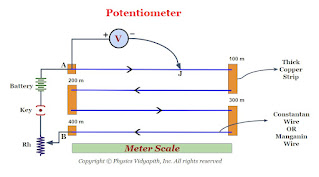 |
| Diagram of Potentiometer |
Metre Bridge OR Slide Wire Bridge
What is Metre Bridge?
$\frac{P}{Q}=\frac{R}{S}$
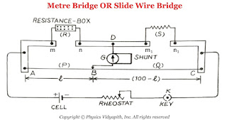
Construction: It consists of usually one-meter long manganin wire of uniform cross-section, stretched along a meter scale fixed over a wooden board and with its two ends soldered to two L-shaped thick copper strips $A$ and $C$. Between these two copper strips, another copper strip is fixed so as to provide two gaps $mn$ and $m_{1}n_{1}$. A resistance box (R.B.) is connected in the gap $mn$ and the unknown resistance $S$ is connected in the gap $m_{1}n_{1}$. A cell of emf $E$, Key $(K)$, and rheostat are connected across $AC$. A movable jockey and a galvanometer are connected across the $BD$, as shown in the figure.
Working:
In a Metre bridge, First take out the suitable resistance $R$ from the resistance box after that move the jockey along the wire $AC$ till there is not any deflection in the galvanometer. This is the condition of a balanced Wheatstone's bridge. If $P$ and $Q$ are the resistance of the part $AB$ and $BC$ of the wire, then for the balanced condition of the bridge, we have,
$\frac{P}{Q}=\frac{R}{S} \qquad(1)$
Let us consider:
The total length of the wire $AC=100 \: cm$
Length of the part $AB$ of wire = $l \: cm$
Length of the part $BC$ of wire = $(100-l) \: cm$
Resistance per unit length of the wire = $\sigma$
Resistance of wire of uniform cross-section = $\infty$
$\frac{P}{Q}=\frac{Resistance \: of \: AB}{Resistance \: of \: BC}$
$\frac{P}{Q}=\frac{\sigma l }{\sigma \left( 100-l \right) }$
$\frac{P}{Q}=\frac{ l }{ \left( 100-l \right) } \qquad (2)$
Now substitute the value of equation $(2)$ in equation $(1)$ then we get
$\frac{R}{S}=\frac{ l }{ \left( 100-l \right) } $
$S=\frac{R(100-l)}{l}$
Where
$S$ → Unknown Resistance
$R$ →Standard Resistance
It is the simplest practical application of the Wheatstone's bridge that is used to measure an unknown resistance.
Principle: Its working is based on the principle of Wheatstone's Bridge.
When the Wheatstone's bridge is balanced
 |
| Metre Bridge Or Slide Wire Bridge |
Length of the part $AB$ of wire = $l \: cm$
Length of the part $BC$ of wire = $(100-l) \: cm$
Resistance per unit length of the wire = $\sigma$
Resistance of wire of uniform cross-section = $\infty$
$R$ →Standard Resistance
Wheatstone's Bridge
It is an arrangement of four resistance used to determine one of this resistance quickly and accurately in terms of the remaining three resistance.
Objective:
To find the unknown resistance with the help of the remaining three
resistance.
Principle of Wheatstone Bridge: The principle of Wheatstone bridge is based on the
principle of Kirchhoff's Law.
Construction:
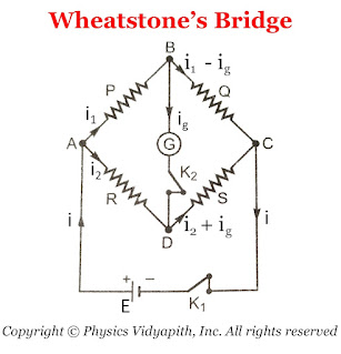
A Wheatstone bridge consists of four resistance $P$,$Q$,$R$, and $S$. This resistance is connected to form quadrilateral $ABCD$. A battery of EMF $E$
is connected between point $A$ and $C$ and a sensitive galvanometer is connected
between point $B$ and $D$ Which is shown in the figure below.
Working:
To find the unknown resistance $S$, The resistance $R$ is to be adjusted
like there is no deflection in the galvanometer. which means that there is not
any flow of current in the arm $BD$. This condition is called "Balanced
Wheatstone bridge" i.e
$\frac{P}{Q}=\frac{R}{S}$
Derivation of Balanced Condition of Wheatstone's Bridge: In accordance with
Kirchhoff's first law, the currents through various branches are shown in the figure
above.
For Close Loop $ABDA$
$0=P \: I_{1} - R \: I_{2} +G \: I_{g} \qquad(1)$
For Close Loop $CBDC$
$0=Q \left( I_{1} - I_{g} \right) -S \left( I_{2} + I_{g} \right) - G\: I_{g}
\qquad(2)$
For Balanced Wheatstone Bridge: $I_{g}=0$
SO from equation $(1)$ and equation $(2)$
$0=P \: I_{1} - R \: I_{2} $
$P \: I_{1} = R \: I_{2} \qquad(3)$
$0=Q I_{1} -S I_{2}$
$Q I_{1} = S I_{2} \qquad(4)$
Now divide the equation $(4)$ and equation $(3)$, then we get
$\frac{P}{Q}=\frac{R}{S}$
 |
| Diagram of Wheatstone's Bridge |
Kirchhoff's laws for an electric circuits
Kirchhoff's laws: Kirchhoff had given two laws for electric circuits i.e.
- Kirchhoff's Current Law or Junction Law
- Kirchhoff's Voltage Law or Loop Law
- Kirchhoff's Current Law or Junction Law: Kirchhoff's current law state that
The algebraic sum of all the currents at the junction in any electric circuit is always zero.$\sum_{1}^{n}{i_{n}}=0$Sign Connection: While applying the KCL, the current moving toward the junction is taken as positive while the current moving away from the junction is taken as negative.
So from figure,the current $i_{1}$,$i_{2}$,$i_{5}$ is going toward the junction and the current $i_{3}$,$i_{4}$, So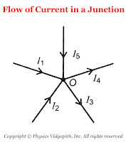
The flow of Current in a junction $\sum{i}= i_{1}+i_{2}+(-i_{3})+(-i_{4})+i_{5}$According to KCL $\sum{i}= 0$, Now the above equation can be written as$i_{1}+i_{2}+(-i_{3})+(-i_{4})+i_{5}=0 \qquad$$i_{1}+i_{2}+i_{5}=i_{3}+i_{4}$Thus, the sum of current going towards the junction is equal to the sum of current going away from the junction.In other words, at any junction, neither the charge accumulates nor the charge is removed. So this law represents conservation of charge. -
Kirchhoff's Voltage Law or Loop Law: Kirchhoff's voltage law state that:
The algebraic sum of all the voltage or emf in any closed loop of an electric circuit is always zero.$\sum_{1}^{n}{E_{n}}=0$This means that the algebraic sum of all the emf applied in any closed loop is always equal to the algebraic sum of the product of current and resistance in the closed loop.$\sum{E}=\sum {i.R}$Sign Connection: While applying this law, a product of current and resistance is taken as positive when we traverse in the direction of the conventional current and the emf is taken positively when we traverse from negative to the positive electrode through the electrolyte.
So from the figure: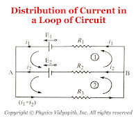
Distribution of Current in a Loop of Circuit For Mesh $(1)$$E_{1}-E_{2}=i_{1}R_{1}-i_{2}R_{2} \qquad(1)$For Mesh $(2)$$E_{2}=i_{2}R_{2}+\left( i_{1}+i_{2} \right)R_{3} \qquad(2)$
Displacement Current
Description of Displacement Current:
The concept of displacement current was first introduced by Maxwell purely on the theoretical ground.
Maxwell postulates that "It is not only current in a conductor that produces a magnetic field but a changing electric field (or time varying electric field) in vacuum or in dielectric also produces the magnetic field. It means that a changing electric field is equivalent to a current which flows as long as the electric field is changing. This equivalent current in a vacuum or dielectric produces the same magnetic effect as an ordinary or conductor current in a conductor. This equivalent current is known as displacement current".
According to the Maxwell modified ampere's law.
$\oint \overrightarrow{B}. \overrightarrow{dl}= \mu_{\circ}i+\mu_{\circ}i_{d}$
Where $i_{d}$ = Displacement Current
Popular Posts
-
Angle of Acceptance → "If incident angle of light on the core for which the incident angle on the core-cladding interface equals t...
-
Let $S$ be a point monochromatic source of light of wavelength $\lambda$ placed at the focus of collimating lens $L_{1}$. The light beam is ...
-
Maxwell's Equations: Maxwell's equation of the electromagnetic wave is a collection of four equations i.e. Gauss's law of elec...
-
Derivation of interference of light due to a wedge-shaped thin film: Interference of light due to wedge-shaped thin film The wedge...
-
Let a plane wavefront be incident normally on slit $S_{1}$ and $S_{2}$ of equal $e$ and separated by an opaque distance $d$.The diffracted l...
Study-Material
Categories
Alternating Current Circuits
(10)
Atomic and Molecular Physics
(4)
Biomedical
(1)
Capacitors
(6)
Classical Mechanics
(12)
Current carrying loop in magnetic field
(5)
Current Electricity
(10)
Dielectric Materials
(1)
Electromagnetic Induction
(3)
Electromagnetic Wave Theory
(23)
Electrostatic
(22)
Energy Science and Engineering
(2)
Error and Measurement
(2)
Gravitation
(10)
Heat and Thermodynamics
(3)
Kinematics Theory Of Gases
(1)
Laser System & Application
(15)
Magnetic Effect of Current
(9)
Magnetic Substances
(3)
Mechanical Properties of Fluids
(4)
Nanoscience & Nanotechnology
(4)
Nuclear Physics
(7)
Numerical Problems and Solutions
(1)
Optical Fibre
(5)
Optics
(25)
Photoelectric Effect
(3)
Quantum Mechanics
(33)
Relativity
(8)
Semiconductors
(2)
Superconductors
(1)
Topic wise MCQ
(9)
Units and Dimensions
(1)
Waves
(5)


