Absorption, Spontaneous Emission and Stimulated Emission of Radiation

Description of the absorption process:

When photons of appropriate energy are incident on lower-energy state atoms, these atoms absorb the photons and go from the lower-energy state to a higher or excited energy state. This process is called absorption.

$A + h\nu \rightarrow A^{*}$

Where

$A \rightarrow$ Lower energy state of the atom
$A^{*} \rightarrow$ Higher or excited energy state of the atom
Absorption Process in Laser
Mathematical Analysis of Absorption:

Let us consider, Two energy states $E_{1}$ and $E_{2}$ having population $N_{1}$ and $N_{2}$ respectively so

The rate of absorption transition for energy state $E_{1}$

$R_{abs}= -\frac{dN_{1}}{dt} \qquad(1)$

Where $\left(-\frac{dN_{1}}{dt}\right)$ shows that the rate of decrease in the population at the lower energy level $E_{1}$

The rate of absorption transition for energy state $E_{2}$

$R_{abs}= \frac{dN_{2}}{dt} \qquad(2)$

Where $\left(\frac{dN_{2}}{dt}\right)$ shows that the rate of increase in population at the higher energy level $E_{2}$

The rate of absorption depends upon the following factors:

1.) The rate of absorption is directly proportional to the population $N_{1}$ of the lower energy state $E_{1}$

$R_{abs}\propto N_{1} \qquad(3)$

2.) The rate of absorption is directly proportional to the energy density $\rho(v)$ of incident light on the lower energy state $E_{1}$

$R_{abs} \propto \rho(v) \qquad(4)$

From equation $(3)$ and equation $(4)$

$R_{abs} \propto N_{1} \rho(v) $

$R_{abs} = B_{12} N_{1} \rho(v) \qquad(5)$

Where $B_{12}$ is called the Einstein coefficient for induced absorption and it indicates the probability of an induced transition from energy state $E_{1} \: \rightarrow \: E_{2}$

At thermal equilibrium, the population (i.e., number of atoms per unit volume in the energy state) of the lower energy state is much larger than that in the higher energy state. So when light propagates through the medium then it gets absorbed.

Important features of the absorption process in a laser:

1.) The energy of the incident photon must be equal to the energy gap between the two energy states.

2.) Absorption is not directional. Atoms absorb photons coming from any direction.

3.) For absorption, the population of the lower energy state must be greater than the population of the higher energy state.

4.) The rate of absorption is a very fast process, occurring in nanoseconds or less.

5.) The rate of absorption helps define the gain coefficient and overall efficiency of the laser medium.

Description of the spontaneous emission process:

When the atom absorbs the energy incident it goes from a lower energy state to a higher energy state, In a higher energy state, the atom can not stay for a long time because the average lifetime of a higher energy state is $10^{-8}$ sec and atom emit the photon spontaneously and then comes from higher energy state to lower energy state. The process is called spontaneous emission.

$A^{*} \rightarrow A + h\nu$

Where

$A \rightarrow$ Lower energy state of the atom
$A^{*} \rightarrow$ Higher or excited energy state of the atom
Spontaneous Emission Process in Laser
Mathematical Analysis of Spontaneous Emission:

Let us consider, Two energy states $E_{1}$ and $E_{2}$ having population $N_{1}$ and $N_{2}$ respectively. So

The rate of spontaneous emission transition for energy state $E_{2}$

$R_{sp}= -\frac{dN_{2}}{dt} = -\frac{N_{2}}{\tau_{sp}} \qquad(1)$

Where $\left(-\frac{dN_{2}}{dt}\right)$ shows that the rate of decrease in the population at the higher energy level $E_{2}$

The rate of absorption depends upon only:

* The rate of spontaneous emission is directly proportional to the population $N_{2}$ of the higher energy state $E_{2}$

$R_{sp}\propto N_{2} \qquad(2)$

$R_{sp} \propto N_{2}$

$R_{sp} = A_{21} N_{2} \qquad(3)$

Where $A_{21}$ is called the Einstein coefficient for spontaneous emission, and it is a function of the frequency and properties of the material. It indicates the probability of spontaneous emission transition from energy state $E_{2} \: \rightarrow \: E_{1}$

The process of spontaneous emission is independent of the light energy.

From equation $(2)$ and equation $(3)$

$ -\frac{N_{2}}{\tau_{sp}} = A_{21} N_{2}$

$-\frac{1}{\tau_{sp}} = A_{21}$

$A_{21} = -\frac{1}{\tau_{sp}} \qquad(4)$

Important features of the spontaneous process in a laser:

1. The spontaneous emission is not amenable to control from outside.

2. It is essentially probabilistic in nature.

3. The light is not monochromatic because of various line-broadening processes.

4. Due to a lack of directionality, the light spreads in all directions around the source. The light intensity decreases rapidly with distance from the source.

5. The light is incoherent.

6. An atom can radiate into any of the $4 \pi$ steradians with any sense of polarization.

Description of the stimulated emission process:

When the higher energy state (or excited state) atom interacts with a photon of appropriate energy, the photon triggers that atom to transition to the lower energy state and emit two photons. This process is called stimulated emission.

$A^{*} + h\nu \rightarrow A + 2 h\nu$

Where

$A$ - Atom of the lower energy state.
$A^{*}$ - Atom of the excited energy state.
Stimulated Emission Process in Laser

Mathematical analysis of the stimulated emission process:

Let us consider, Two energy states $E_{1}$ and $E_{2}$ which have population $N_{1}$ and $N_{2}$ respectively so

The stimulated transition's rate for energy state $E_{2}$

$R_{st}= -\frac{dN_{2}}{dt} \qquad(1)$

Where $\left(-\frac{dN_{2}}{dt}\right) \rightarrow$ Decrease in population's rate at the higher energy state $E_{2}$

The rate of absorption depends upon the following factors:

1.) The stimulated transition's rate is directly proportional to the population $N_{2}$ of the higher energy state $E_{2}$

$R_{st}\propto N_{2} \qquad(2)$

2.) The stimulated transition's rate is directly proportional to the energy density $\rho(v)$ of incident light on the higher energy state $E_{2}$

$R_{st} \propto \rho(v) \qquad(3)$

From equation $(2)$ and equation $(3)$

$R_{st} \propto N_{2} \rho(v) $

$R_{st} = B_{21} N_{1} \rho(v) \qquad(5)$

Where $B_{21}$ is called the Einstein coefficient for stimulated emission and it indicates the probability of a stimulated transition from energy state $E_{2} \: \rightarrow \: E_{1}$.


Important features of the stimulated emission:

1.) The process of stimulated emission can be influenced or controlled from outside the system.

2.) The photon generated through stimulated emission propagates along the same path as the stimulating photon.

3.) The photon produced through stimulated emission is identical to the incident photon for its frequency, phase, and polarization.

4.) The light produced through stimulated emission is directional, coherent, and monochromatic.

5.) Light Amplification: 
Multiplication of Stimulated Photon into an Avalanche
One of the most remarkable aspects of stimulated emission is the multiplication of photons (i.e., exponential growth). When a single photon strikes an excited atom, it emits two photons. These two emitted photons are in the same phase and direction. These two photons stimulate two excited atoms in their path and produce a total of four photons, which are in the same phase and direction. This process continues, and the number of photons builds up in an avalanche-like manner.
Amplification of Laser Light
Since all the emitted light waves originate from a single initial photon and maintain the same phase, the waves are coherent and interfere constructively. As the coherent wave passes through the medium filled with excited atoms, its amplitude increases with each additional stimulated photon. This results in a continuous amplification of light, forming the basis of how lasers work.

6.) High Intensity: Because of constructive interference of the waves, the net intensity of the resultant light will be proportional to the square of the number of atoms emitting light. Thus

$I_{Total}=N^{2} I$

Hence, the light produced due to stimulated emission is of very higher intensity than the light generated through spontaneous emissions.

Einstein Coefficient Relation

Derivation of Einstein Coefficient Relation→ Let us consider the $N_{1}$ and $N_{2}$ is the mean population of lower energy state and upper energy state respectively. If the energy density of incident light is $\rho(\nu)$ then

The rate of transition of number of atoms due to absorption process:

$R_{abs}=B_{12} \: \rho(v) \: N_{1} \qquad(1)$

The above equation shows the number of atoms absorbing the photon per second per unit volume

Where $B_{12}$= Einstein Absorption Coefficent

The rate of transition of number of atoms due to sponteneous emission process:

$R_{sp}=A_{21} \: N_{2} \qquad(2)$

The above equation shows the number of atoms emitting the photon per second per unit volume due to spontaneous emission

Where $A_{21}$= Einstein Spontaneous Emission Coefficient

The rate of transition of the number of atoms due to stimulated emission process:

$R_{st}=B_{21} \: \rho(v) \: N_{2} \qquad(3)$

The above equation shows the number of atoms emitting the photon per second per unit volume due to stimulated emission

Where $B_{21}$= Einstein Stimulated Emission Coefficient

Under the thermal equilibrium, the mean population $N_{1}$ and $N_{2}$ in lower and upper energy states respectively must remain constant. This condition requires that the transition of the number of atoms from $E_{2}$ to $E_{1}$ must be equal to the transition of the number of atoms from $E_{1}$ to $E_{2}$. Thus

$\left.\begin{matrix}The \: number \: of \: atoms \: absorbing \\ photons \: per \: second \: per \: unit \: volume \end{matrix}\right\} \\ = \left.\begin{matrix} The \: number \: of \: atoms \: emitting \\ photons \: per \: second \: per \: unit \: volume \end{matrix}\right\}$

i.e $R_{abs}= R_{sp}+R_{st}$

$B_{12} \: \rho(v) \: N_{1}= A_{21} \: N_{2} + B_{21} \: \rho(v) \: N_{2}$

$B_{12} \: \rho(v) \: N_{1} - B_{21} \: \rho(v) \: N_{2} = A_{21} \: N_{2} $

$ \rho(v) (B_{12} \: N_{1} - B_{21} \: N_{2} ) = A_{21} \: N_{2} $

$\rho(v)=\frac{A_{21} \: N_{2}}{(B_{12} \: N_{1} - B_{21} \: N_{2} )} \qquad(4)$

We know that

$\frac{N_{1}}{N_{2}}=e^{\frac{(E_{2}-E_{1})}{kT}}$

$\frac{N_{1}}{N_{2}}=e^{\frac{h\nu}{kT}}$

Now substitute the value of $\frac{N_{1}}{N_{2}}$ in equation $(4)$

$\rho(v)=\frac{A_{21}}{B_{12}} \left [ \frac{1}{e^{\frac{h\nu}{kT}}- \frac{B_{21}}{B_{12}}} \right ] \qquad(5)$

According to Planck's Radiation Law

$\rho(v)=\frac{8\pi h \nu^{3}}{c^{3}} \left [ \frac{1}{e^{\frac{h\nu}{kT}}- 1} \right ] \qquad(6)$

Now comparing the equation $(5)$ and equation $(6)$

$\frac{B_{21}}{B_{12}}=1$ and $\frac{A_{21}}{B_{12}}=\frac{8\pi h \nu^{3}}{c^{3}}$

From the above equation, we get

$B_{21}=B_{12}$

$B_{12}=B_{21}=\frac{c^{3}}{8\pi h \nu^{3}}A_{21}$

Laser and properties of a Laser beam

Basic Definition of Laser→

LASER $\rightarrow$ Light Amplification by Stimulated Emission of Radiation.

Definition:

It is a device that produces a highly intense, monochromatic, collimated, and highly coherent light beam. Laser action mainly depends on the phenomenon of population inversion and stimulated emission.

The first successful Laser is a solid-state laser built by TH Maiman in 1960 using Ruby as an active medium.

Note→

The laser has often been referred to as an optical MASER because it operates in the visible spectrum portion of spectrum. In general, when the variation occurs below the infrared portion of the electromagnetic spectrum, the term MASER will be employed, and when stimulated emission occurs in the infrared, visible, or ultraviolet portion of the spectrum, the term laser or optical MASER will be used.

Properties of a Laser Beam→

The laser beam has the following main characteristics:

1.) A laser beam has high directionality and can be emitted only in one direction. The divergence of the laser beam can be less than $10^{-5}$ radian. Due to high directionality, these beams can be focused in very small areas.

2.) A laser beam is very narrow and hence can travel long distances without any spread. The spectral width ($\Delta \lambda$)of a laser beam is of the order of $10^{-6} A^{\circ}$.

3.) A laser beam is highly monochromatic. Its monochromaticity is much more than that of any conventional monochromatic source.

4.) The laser beam has high intensity and high power levels that can produce a temperature of the order of $10^{4} \: ^{\circ}C$.

5.) A laser beam has a high degree of coherence. It is highly temporally and spatially coherent.

Missing Order in double slit diffraction pattern

The equation for missing order in the double-slit diffraction pattern→ The nature of the diffraction pattern due to the double slits depends upon the relative values of $e$ and $d$. If, however, $e$ is kept constant and $d$ is varied, then certain orders of interference maxima will be missing.

We know that, the direction of interference maxima

$(e+d)\:sin\theta=\pm n\lambda \qquad(1)$

The direction of diffraction minima

$e \: sin\theta=\pm m\lambda \qquad(2)$

Divide the equation $(1)$ by equation $(2)$

$\frac{(e+d)}{e}=\frac{n}{m}$

Case (I)→

If $e=d$ then

n=2m

So for $m=1,2,3,....$

The $n=2,4,6,....$

Thus, the $2_{nd}, 4^{th}, 6^{th}, ...$ order interference maxima will be missing.

Case (II) →

If $e=\frac{d}{2}$ then

n=3m

So for $m=1,2,3,....$

The $n=3,6,9,....$

Thus, the $3_{rd}, 6^{th}, 9^{th}, ...$ order interference maxima will be missing.

Diffraction due to a plane diffraction grating or N- Parallel slits

A diffraction grating (or $N$-slits) consists of a large number of parallel slits of equal width and separated from each other by equal opaque spaces.

It may be constructed by ruling a large number of parallel and equidistance lines on a plane glass plate with the help of a diamond point. the duplicates of the original grating are prepared by pouring a thin layer of colloidal solution over it and then allowed to Harden. This layer is then removed from the original grating and fixed between two glass plates which serve as a plane transmission grating. Generally, A plane transmission grating has 10000 to 15000 lines per inch.
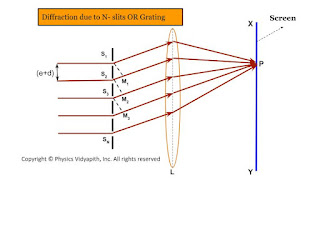
Diffraction due to N- slits OR Grating

Theory→

Since plane diffraction grating is an $N$-slit arrangement, the deflection pattern due to it will be the combined diffraction effect of all such slits. Let a plane wavefront of monochromatic light be incident normally on the $N$-parallel slit of the gratings. Each point within the slits then sends out secondary wavelets in all directions.

Let $e$ be the width of each slipped and $d$ be the separation between any two consecutive slits then $(e+d)$ is known as the grating element. The diffracted ray from each slit, then $(e+d)$ is knowns as the grating element. The diffracted ray from each slit is focussed at a point $P$ on the screen $XY$ with the help of a convex lens $L$.

Expression for Intensity→

Let $S_{1}, S_{2}, S_{3},.......$ be the middle point of each slit and $S_{1}M_{1}, S_{2}M_{2}, S_{3}M_{3}, ........S_{N-1}M_{N-1}$ be the perpendicular drawn as shown in the figure.The waves diffracted from each slit are equivalent to a single wave amplitude:

$R=\frac{A\:sin\alpha}{\alpha} \qquad(1)$

The path difference between the waves from slit $S_{1}$ and $S_{2}$ is

$S_{2}M_{1}=(e+d)sin\theta$

The path difference between the waves from slit $S_{2}$ and $S_{3}$ is

$S_{3}M_{2}=(e+d)sin\theta$

The path difference between the waves from slit $S_{n-1}$ and $S_{n}$ is

$S_{N}M_{N-1}=(e+d)sin\theta$

Thus, it is obvious that the path difference between all the consecutive waves is the same and equal to $(e+d)sin\theta$

The corresponding phase difference

$\Delta \phi=\frac{2\pi}{\lambda}(e+d)sin\theta \qquad(2)$

Let $\Delta \phi=2\beta$

$\beta=\frac{\pi}{\lambda}(e+d)sin\theta \qquad(3)$

Thus, the resultant amplitude at $P$ is the resultant amplitude of $N$ waves, each of amplitude $R$ and its common phase difference is $(2\beta)$

$R'=\frac{R \: sin \left( \frac{2N\beta}{2} \right) }{sin \left( \frac{2\beta}{2} \right)} \qquad(4)$

The resultant amplitude at $P$

$R'=\frac{R \: sin N\beta}{sin \beta} $

Where $R=\frac{A\: sin\alpha}{\alpha}$. Now substitute the value of $R$ in the above equation and we get

$R'= \frac{A\: sin\alpha}{\alpha} \frac{ \: sin N\beta}{sin \beta} \qquad(5)$

The resultant intensity at $P$

$I=R'^{2}$

$I=\frac{A^{2} \: sin^{2} \alpha}{\alpha^{2}} \frac{ \: sin^{2} N\beta}{sin^{2} \beta} \qquad(6)$

The factor $\frac{A^{2} \: sin^{2} \alpha}{\alpha^{2}}$ gives the intensity pattern due to diffraction from a single slit while the factor $\frac{ \: sin^{2} N\beta}{sin^{2} \beta}$ gives the distribution of intensity due to interference from all the $N$-slit

Principle Maxima→

The intensity will be maximum when $sin\beta=0$ or $\beta=\pm n\pi$

Where $n=0,1,2,3,.....$

But under this condition, $sinN\beta$ is also equal to zero. Hence term $\frac{sin N\beta}{sin \beta}$ can be solve by

$\lim_{\beta \rightarrow \pm n\pi} \frac{ \: sin N\beta}{sin \beta}=\lim_{\beta \rightarrow \pm n\pi} \frac{\frac{d}{d\beta} (sin N\beta)}{\frac{d}{d\beta}(sin \beta)}$

$\lim_{\beta \rightarrow \pm n\pi} \frac{ \: sin N\beta}{sin \beta}=\lim_{\beta \rightarrow \pm n\pi} \frac{N cos N\beta}{cos \beta}$

$\lim_{\beta \rightarrow \pm n\pi} \frac{ \: sin N\beta}{sin \beta}=N \lim_{\beta \rightarrow \pm n\pi} \frac{ cos N\beta}{cos \beta}$

Where the value of $\lim_{\beta \rightarrow \pm n\pi} \frac{ cos N\beta}{cos \beta}=1$

$\lim_{\beta \rightarrow \pm n\pi} \frac{ \: sin N\beta}{sin \beta}=N \qquad(7)$

So the maximum intensity

$I=\frac{A^{2} \: sin^{2} \alpha}{\alpha^{2}} N^{2} \qquad(8)$

Thus, the condition for principle maxima

$sin \beta=0$

$\beta=\pm n\pi$

$(e+d)sin\theta=\pm n \lambda \qquad(9)$

For $n=0$, we get $\theta=0$ This $\theta=0$ gives the direction of zero-order principal maxima. For the value of $n=1,2,3,......$, gives the direction of first, second, third,....... order principal maxima.

Minima →

The intensity will be minimum, when $sin N\beta=0$ but $sin\beta=0$

$N\beta=\pm m\pi$

$N(e+d)sin\theta=\pm m \lambda \qquad(10)$

Where $m$ can take all integral values except $0, N,2N,3N,......$ because for these values of $m$, $sin\beta=0$ which gives the position of principal maxima.

Secondary maxima→

It is obvious from the above condition of minima, there are $(N-1)$ minima between two successive principal maxima. Hence, there are $(N-2)$ other maxima with alternative minima between two successive principal maxima. These $(N-2)$ maxima are called secondary maxima. To find the condition of secondary maxima equation $(6)$ is differentiated with respect to $\beta$ and equated to zero.

$\frac{dI}{d\beta}= \frac{A^{2}\:sin^{2}\alpha}{\alpha^{2}}2 \frac{sinN\beta}{sin\beta} \left [\frac{sin\beta . N. cosN\beta-sinN\beta . cos\beta}{sin^{2}\beta} \right ]$

$0= \frac{A^{2}\:sin^{2}\alpha}{\alpha^{2}}2 \frac{sinN\beta}{sin\beta} \left [\frac{sin\beta . N. cosN\beta-sinN\beta . cos\beta}{sin^{2}\beta} \right ]$

$N.sin\beta . cosN\beta - sinN \beta . cos\beta=0$

$\tan N\beta = N tan \beta \qquad(11)$

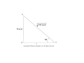
Now construct a right-angled triangle with the sides according to the above equation$(11)$
Right-angled Triangle for Intensity Calculation
From the above triangle:

$sinN\beta=\frac{N tan\beta}{\sqrt{1+N^{2}tan^{2}\beta}} \qquad(12)$

Substituting the value of $sinN\beta$ from the above equation to equation (6)

$I=\frac{A^{2} \: sin^{2} \alpha}{\alpha^{2}} \frac{N^{2} tan^{2}\beta}{1+N^{2}tan^{2}\beta} \frac{ 1}{sin^{2} \beta}$

$I=\frac{A^{2} \: sin^{2} \alpha}{\alpha^{2}} \frac{N^{2}}{1+N^{2}tan^{2}\beta} \frac{ 1}{cos^{2} \beta} \qquad \left(\because tan\beta =\frac{sin\beta}{cos\beta} \right)$

$I=\frac{A^{2} \: sin^{2} \alpha}{\alpha^{2}} \frac{N^{2}}{cos^{2} \beta+N^{2}sin^{2}\beta} $

$I=\frac{A^{2} \: sin^{2} \alpha}{\alpha^{2}} \frac{N^{2}}{1- sin^{2} \beta+N^{2}sin^{2}\beta} $

$I=\frac{A^{2} \: sin^{2} \alpha}{\alpha^{2}} \frac{N^{2}}{1+(N^{2}-1) sin^{2} \beta} \qquad(12)$

Now divide the equation $(12)$ by equation $(8)$ so

$\frac{Intensity\: of\:secondary\:maxima}{Intensity\:of\:principal\:maxima}=\frac{1}{1+(N^{2}-1) sin^{2} \beta}$

It is obvious from the above equation that When $N$ increases then the intensity of secondary maxima decreases.

Intensity distribution diagram due to a diffraction grating

Fraunhofer diffraction due to a double slit

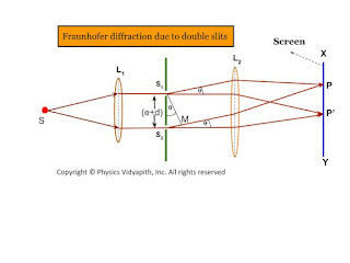
Let a plane wavefront be incident normally on slit $S_{1}$ and $S_{2}$ of equal $e$ and separated by an opaque distance $d$.The diffracted light is focused on the screen $XY$. The diffracted pattern on the screen consists of equally spaced bright and dark fringe due to interference of light from both the slits and modulated by diffraction pattern from individual slits. op

The diffraction pattern due to double-slit can be explained considering the following points →
  • All the points in slits $S_{1}$ and $S_{2}$ will send secondary waves in all directions.

  • All the secondary waves moving along the incident wave will be focussed at $P$ and the diffracted waves will be focussed at $P'$

  • The amplitude at $P'$ is the resultant from two slit each of amplitude $R=\frac{A\:sin\alpha}{\alpha}$

  • T two waves from two-slit $S_{1}$ and $S_{2}$ will interfere at $P'$

  • Fraunhofer diffraction due to double slits
    Fraunhofer diffraction due to double slits

    Expression for Intensity →

    $\Delta = S_{2}M$

    $\Delta=(e+d)sin\theta\qquad(1)$

    The corresponding phase difference →

    $\Delta\phi= \frac{2\pi}{\lambda}(e+d)sin\theta \qquad(2)$

    Let $\Delta \phi =2 \beta \qquad(3)$

    $\beta=\frac{\pi}{\lambda}(e+d)sin\theta\qquad(4)$

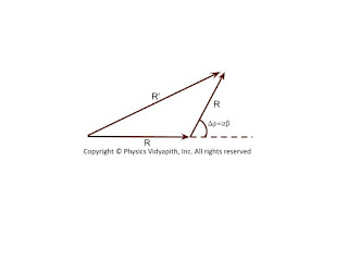
    The resultant amplitude at $P'$ can be obtained by the vector addition method. The resultant amplitude at $P'$
    Resultant Vector
    Resultant Vector
    $R'^{2}=R^{2}+R^{2}+2R.R.cos\Delta\phi$

    $R'^{2}=R^{2}+R^{2}+2R.R.cos2\beta$ {\qquad $\because 2\beta=\Delta\phi$}

    $R'^{2}=2R^{2}+2R^{2}cos2\beta$

    $R'^{2}=2R^{2} \left( 1+cos2\beta \right)$

    $R'^{2}=4R^{2} cos^{2}\beta \qquad(5)$

    Where $R$ - Resultant amplitude of each slit $S_{1}$

    $R=\frac{A\: sin\alpha}{\alpha} \qquad(6)$

    Substituting the value of $R$ in equation $(5)$

    $R'^{2}=4 A^{2} \frac{sin^{2}\alpha}{\alpha^{2}} cos^{2} \beta \qquad(7)$

    $R'=2 A \frac{sin\alpha}{\alpha} cos\beta \qquad(8)$

    The intensity of the resultant diffraction pattern at $P'$

    $I=4 A^{2} \frac{sin^{2}\alpha}{\alpha^{2}} cos^{2} \beta \qquad(9)$

    Where $\alpha=\frac{\pi}{\lambda}e\:sin\theta \qquad(10)$

    The resultant intensity at any point is the contribution of the following two factors →

  • The factor $\frac{A^{2}sin^{2}\alpha}{\alpha^{2}}$, represents the intensity distribution due to diffraction from any individual slits.

  • The factor $cos^{2}\beta$ represents the intensity distribution due to interference of waves from two parallel slits.

  • Condition for Maxima and Minima →
    1. Maxima and minima due to diffraction term
    2. Maxima and minima due to interference term

    1. Maxima and minima due to diffraction term →

    i.) Principal Maxima →

    The diffraction term $\frac{A^{2}sin^{2}\alpha}{\alpha^{2}}$ gives the central maxima, for $\alpha=0$ so

    $\frac{\pi}{\lambda}e\: sin\theta=0$

    $sin\theta =0 $

    $\theta=0$

    ii.) Minima →

    The diffraction term $\frac{A^{2}sin^{2}\alpha}{\alpha^{2}}$ gives the central minima, for $sin\alpha=0$ so

    $\alpha=\pm m\pi$

    $e\:sin\theta=\pm m\pi$

    iii.) Secondary Maxima →

    The secondary maxima are obtained in the direction given by →

    $\alpha= \pm\frac{3\pi}{2},\pm\frac{5\pi}{2},\pm\frac{7\pi}{2},..............$

    2. Maxima and minima due to interference term →

    i.) Maxima

    The interference term $cos^{2}\beta$ gives maxima in the direction →

    $cos^{2}=1$

    $\beta=\pm n \pi$

    $\frac{\pi}{\lambda}(e+d)sin\theta= \pm n \pi$

    $(e+d)sin\theta= \pm n \lambda$

    Where $n=0,1,2,3,.....$

    In the direction $\theta=0^{\circ}$, the principle maxima due to interference and diffraction coincide.

    ii.) Minima

    The interference term $cos^{2}\beta$ gives minima in the direction →

    $cos^{2}\beta=0$

    $\beta=\pm(2n+1)\frac{\pi}{2}$

    $(e+d)sin\theta=\pm(2n+1)\frac{\pi}{2}$

    The intensity distribution curve due to the diffraction term, interference term, and the combined effect is shown in the figure below →
    Intensity diagram of Fraunhofer double slit Experiment
    Intensity diagram of Fraunhofer double slit Experiment

    Dispersive power of plane diffraction grating and its expression

    Dispersive power of plane diffraction grating:

    The dispersive power of a diffraction grating is defined as:

    The rate of change of the angle of diffraction with the change in the wavelength of light are called dispersive power of plane grating.

    If the wavelenght changes from $\lambda$ to $\lambda +d\lambda$ and respective change in the angle of diffraction be from $\theta$ to $\theta+d\theta$ then the ratio $\left(\frac{d\theta}{d\lambda} \right)$

    Expression of Dispersive power of a plane diffraction grating:

    The grating equation for a plane transmission grating for normal incidence is given by

    $(e+d)sin\theta=n\lambda \qquad(1)$

    Where$(e+d)$ - Grating Element$\qquad \:\: \theta$ - Diffraction angle for spectrum of $n^{th}$ order

    Differentiating equation $(1)$ with respect to $\lambda$, we have

    $(e+d)cos\theta \left( \frac{d\theta}{d\lambda} \right)=n$

    $\frac{d\theta}{d\lambda}=\frac{n}{(e+d)cos\theta}$

    $\frac{d\theta}{d\lambda}=\frac{n}{(e+d)\sqrt{1-sin^{2}\theta}} \qquad(2)$

    Now substitute the value of $sin\theta$ from equation$(1)$ in equation$(2)$

    $\frac{d\theta}{d\lambda}=\frac{n}{(e+d)\sqrt{1- \frac{n^{2}\lambda^{2}}{(e+d)^{2}}}} $

    $\frac{d\theta}{d\lambda}=\frac{1}{\sqrt{\left(\frac{e+d}{n} \right)^{2}}- \lambda^{2}}$

    Here $d\theta$- Angular separation between two lines

    The above equation gives the following conclusions:

  • The dispersive power is directly proportional to the order of spectrum$(n)$

  • The dispersive power is inversely proportional to the grating element $(e+d)$.

  • The dispersive power is inversely proportional to the $cos\theta$ i.e Larger value of $\theta$, higher is the dispersive power.

  • Fraunhofer diffraction due to a single slit

    Let $S$ be a point monochromatic source of light of wavelength $\lambda$ placed at the focus of collimating lens $L_{1}$. The light beam is incident normally from $S$ on a narrow slit $AB$ of width $e$ and is diffracted from it. The diffracted beam is focused at the screen $XY$ by another converging lens $L_{2}$. The diffraction pattern having a central bright band followed by an alternative dark and bright band of decreasing intensity on both sides is obtained.

    Analytical Explanation: The light from the source $S$ is incident as a plane wavefront on the slit $AB$. According to Huygens's wave theory, every point in $AB$ sends out secondary waves in all directions. The undeviated ray from $AB$ is focused at $C$ on the screen by the lens $L_{2}$ while the rays diffracted through an angle $\theta$ are focussed at point $p$ on the screen. The rays from the ends $A$ and $B$ reach $C$ in the same phase and hence the intensity is maximum.
    Fraunhofer diffraction due to a single slit
    Fraunhofer diffraction due to a single slit
    Expression for intensity:

    To find the intensity at $P$, Let us draw normal $AN$ on $BN$. Therefore the path difference between the extreme rays is

    $\Delta=BN$

    $\Delta=AB \: sin \theta$

    $\Delta=e \: sin \theta \qquad(1)$

    Where $AB=e$ (width of the slit)

    The phase difference

    $\Delta \phi =\frac{2 \pi}{\lambda} e \: sin\theta \qquad(2)$ {from eq$(2)$}

    Let AB be divided into a large number $n$ of equal parts then there may be an infinitely large number of the point sources of secondary wavelets between $A$ and $B$. The phase difference between any two consecutive parts is, therefore

    $\frac{1}{n} \Delta \phi=\frac{1}{n} \frac{2 \pi}{\lambda} e \: sin\theta$

    According to the theory of the composition of $n$ vibration each of amplitude $a$ and common phase difference $\delta$ between successive vibrations, the resultant amplitude at $P$ is given by

    $R=a\frac{sin(\frac{n\delta}{2})}{sin(\frac{\delta}{2})} \qquad(4)$

    Put the value of $\delta$ in equation $(4)$ so

    $R=a \frac{sin [(\frac{1}{n} \frac{2\pi}{\lambda}e\: sin \theta) \frac{n}{2}]}{sin [\frac{1}{2}(\frac{1}{n} \frac{2\pi}{\lambda}e\: sin \theta)]}$

    $R=a \frac{sin (\frac{\pi}{\lambda}e\: sin \theta)}{sin [\frac{1}{n} (\frac{\pi}{\lambda}e\: sin \theta)]} \qquad(5)$

    Let $\alpha=\frac{\pi}{\lambda}e\: sin \theta \qquad(6)$

    Then from equation $(5)$

    $R=a \frac{sin \alpha }{sin (\frac{\alpha}{n})} \qquad(7)$

    For the large value of $n$, the value of $\frac{\alpha}{n}$ is very small, Therefore $sin \alpha \approx \frac{\alpha}{n}$

    Then equation $(7)$ can be written as

    $R=a \frac{sin \alpha}{\frac{\alpha}{n}}$

    $R=\frac{na \: sin\alpha}{\alpha}$

    $R=\frac{A \: sin\alpha}{\alpha} \qquad(8)$

    Where $A$ is total amplitude of $n$ vibration.$R$ is resultant amplitude of $n$ vibration

    So the resultant intensity at $P$

    $I=R^{2}$

    $I=\frac{A^{2} \: sin^{2}\alpha}{\alpha^{2}} \qquad(9)$

    Condition for Principle Maxima:

    From equation $(7)$

    $R=\frac{A \: sin\alpha}{\alpha}$

    $R=\frac{A}{\alpha} [\alpha - \frac{\alpha^{3}}{3!} + \frac{\alpha^{5}}{5!} -\frac{\alpha^{7}}{7!} + ..... ]$

    $R=A [1 - \frac{\alpha^{2}}{3!} + \frac{\alpha^{4}}{5!} -\frac{\alpha^{6}}{7!} + .....] $

    If $\alpha=0$ then the resultant amplitude will be maximum then

    $R=A$

    And

    $\frac{\pi}{\lambda}e\: sin \theta = 0$ {From equation $(6)$}

    $sin \theta = 0$

    $sin \theta = sin 0^{\circ}$

    $ \theta = 0^{\circ}$

    The resultant intensity at $P$ will be the maximum. For $\theta=0^{\circ}$ and called the principal maxima. Hence the intensity of the principal maxima:

    $I_{0}=A^{2}$

    Condition for Minima:

    It is clear from equation $(8)$ that the intensity will be minimum when $sin\alpha=0$ but $\alpha \neq 0$ So.

    $sin \alpha =0$

    $sin \alpha= sin (m \pi)$

    $\alpha=\pm m \pi$

    And

    $\frac{\pi}{\lambda}e\: sin \theta = \pm m \pi$ {From equation $(6)$}

    $\frac{\pi}{\lambda}e\: sin \theta = \pm m \pi$

    $ e\: sin \theta = \pm m \lambda$

    The value of $m=1,2,3,4,5,......$ gives the direction of first, second, third,.....minima.

    Condition for Secondary Maxima: In the diffraction pattern, there are secondary maxima in addition to principal maxima. The condition of secondary maxima may be obtained by differentiating equation $(9)$ with respect to $\alpha$ and equating it to zero. Hence

    $\frac{dI}{d\alpha}=\frac{d}{d\alpha} \left( A^{2} \frac{sin^{2}\alpha}{\alpha^{2}}\right)$

    $\frac{dI}{d\alpha}=A^{2} 2 \left(\frac{sin\alpha}{\alpha} \left [\frac{\alpha \: cos\alpha - sin\alpha}{\alpha^{2}} \right ] \right)$

    But for maxima $\frac{dI}{d\alpha}=0$

    So $A^{2} 2 \left(\frac{sin\alpha}{\alpha} \left [\frac{\alpha \: cos\alpha - sin\alpha}{\alpha^{2}}\right ] \right)=0$

    $ \frac{\alpha \: cos\alpha - sin\alpha}{\alpha^{2}}=0$

    $\alpha \: cos\alpha - sin\alpha=0$

    $\alpha=tan\alpha$

    The above equation can be solved graphically by plotting the curves

    $y=\alpha$

    $y=tan\alpha$

    The equation $y=\alpha$ gives the straight line passing through the origin and making an angle $45^{\circ}$ with the x-axis.
    Position of maxima due to diffraction from a single slit
    Position of maxima due to diffraction from a single slit
    The point of intersection of these two curves gives the value of $\alpha$ satisfying the equation $\alpha=tan\alpha$. These points correspond to the value of

    $\alpha= 0, \frac{\pm 3\pi}{2}, \frac{\pm 5\pi}{2}, \frac{\pm 7\pi}{2}, ................$

    The first value $\alpha=0$ gives the position of principle maxima while the value of $\alpha= \frac{\pm 3\pi}{2}, \frac{\pm 5\pi}{2}, \frac{\pm 7\pi}{2}, ................$ gives the position first secondary maxima, second secondary maxima, and third secondary maxima and so on respectively.

    The intensity of the first secondary maxima

    $I_{1}=A^{2} \left [\frac{sin \left(\frac{3\pi}{2} \right)}{\frac{3\pi}{2}} \right ]^{2}$

    $I_{1}=\frac{4}{9\pi^{2}}A^{2}=\frac{A^{2}}{22}=\frac{I_{0}}{22}$

    Similarly, the intensities of secondary maxima

    $I_{2}=A^{2} \left [\frac{sin \left(\frac{5\pi}{2} \right)}{\frac{5\pi}{2}} \right ]^{2}$

    $I_{2}=\frac{4}{25\pi^{2}}A^{2}=\frac{A^{2}}{62}=\frac{I_{0}}{62}$

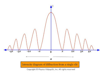
    Thus, It is obvious from the value of $I_{0}, I_{1}, I_{2},.....$, etc that the diffraction pattern consists of a bright central maximum followed by minima of zero intensity and then secondary maxima of decreasing intensity on either side of it.
    Intensity diagram of diffraction from a single slit
    Intensity diagram of diffraction from a single slit

    It is also obvious from the value of $I_{0}, I_{1}, I_{2},.....$, etc that the relative intensities of successive maxima are nearly

    $I_{0}: I_{1}: I_{2}:...=1:\frac{4}{9\pi^{2}}: \frac{4}{25\pi^{2}}: \frac{4}{49\pi^{2}}:...$

    Interference of light and classification of Interference

    Interference of light:

    When two or more waves, having the same frequency and constant phase difference, travel simultaneously in the same region of a medium, these waves superimpose on each other and a resultant wave is obtained which has intensity at some points maximum and some points minimum in the region. This is phenomenon is known as interference of light.

    When the intensity of the resultant wave is maximum in the region then this is called constructive interference.

    when the intensity of the resultant wave is minimum in the region then this is called destructive interference.

    Classification of Interference:

    The phenomenon of interference may be grouped into two categories depending upon the formation of two coherent sources in practice.The interference of light is classified into two categories:

  • Division of amplitude

  • Division of wavefront

  • Division of amplitude:

    In this method, the amplitude of the incident beam is divided into two or more parts are either by partial reflection or refraction. the beams travel in different paths, are superimposed on each other, and form the interference pattern.

    Example: Interference in the thin film, Newton's rings, and Michelson's interferometer are examples of two-beam interference and Fabry-Perot interferometer is the example of multiple-beam interference.

    Division of Wavefront:

    Under this category, the coherent sources are obtained by dividing the wavefront, originating from a common source, by employing mirrors, biprisms, or lenses. This class of interference requires initially a point source or a narrow slit source. The instruments used to obtain coherent sources and hence interference by division of wavefront are fresnel biprism fresnel Mila mirror Lloyd's mirror laser etc.

    Newton's rings in reflected monochromatic light

    Newton's Rings:

    Experimental Arrangement:

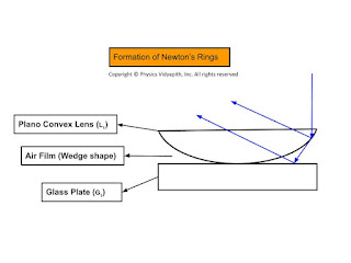
  • A plano-convex lens $l_{1}$ of large radius of curvature is placed on a plane glass plate $G_{1}$ with the curved surface touching the glass plate.

  • An air film is enclosed between the curved surface of the lens and the glass plate.

  • A sodium vapor lamp $S$ is kept at the focus of a biconvex lens $L$ which converts the diverging beam of light into a parallel beam. The parallel beam of light is made to fall on a glass plate $G_{2}$ kept at an angle of $45^{\circ}$ with the incident beam.

  • A part of incident light is reflected toward the plano-convex lens. This light is again reflected back, partially from the top and partially from the bottom of the air fil and transmitted by the glass plate $G_{2}$. The interference of these rays is observed through a microscope $M$.

  • Newtons Rings Experiment Setup-Ray Diagram
    Newtons Rings Experiment Setup-Ray Diagram
    Explanation of the formation of Newton's rings:

  • Division of amplitude takes place at the curved surface of the plano-convex lens.

  • The incident light is partially reflected and partially transmitted at the curved surface.

  • The transmitted ray is reflected from the glass plate. These two rays interfere in reflected light

  • The path difference between these rays depends on the thickness of the air film enclosed between the curved surfaces of the lens and glass plate which increases radially outward from the center. The thickness of the air film is zero at the center

  • Formation of Newton Rings
    Formation of Newton Rings
    Path difference:

    Let $t$ is the thickness of air film at a radial distance of $r$ and $R$ is the radius of curvature. So the path difference for a wedge-shaped film is

    $\Delta=2 \mu t \: cos(r+\alpha) \pm \frac{\lambda}{2} \qquad(1)$

    HereRefractive index of air film ($\mu)=1$$\alpha$ is very small i.e. $\alpha \approx 0$For normal incidence $r=0$ i.e $cos(\alpha+r)=1$

    Now apply the above condition to equation $(1)$ then we get

    $\Delta = 2t + \frac{\lambda}{2} \qquad(2)$

    Newton’s Rings Diagram for Path difference Formula Calculation
    Newton’s Rings Diagram for Path difference Formula Calculation
    Form figure, In $\Delta OAB$, apply the Pythagoras theorem

    $OB^{2}=OA^{2}+AB^{2}$

    $R^{2}=(R-t)^{2}+r^{2}$

    $R^{2}=R^{2}+t^{2}-2Rt+r^{2}$

    $2Rt=t^{2}+r^{2}$

    As $t$ is very small, $t^{2}$ can be neglected in comparison with $r^{2}$. So

    $2Rt=r^{2}$

    $2t=\frac{r^{2}}{R} \qquad(3)$

    Here $r$- Radius of a circle for which thickness is $t$

    If $D$ is the diameter of this circle then

    $r=\frac{D}{2}$

    So from equation $(3)$

    $2t=\frac{D^{2}}{4R} \qquad(4)$

    Substitute the value of $2t$ in equation $(2)$ then we get

    $\Delta = \frac{D^{2}}{4R}+\frac{\lambda}{2}$

    Diameter of Bright rings:

    For bright rings, the condition for constructive interference is satisfied. i.e.

    $\Delta =n \lambda$

    So from the above equations, we get

    $\frac{D^{2}}{4R}+\frac{\lambda}{2}=n \lambda $

    Where $D_{n}$- Diameter of the $n^{th}$ bright ring

    $\frac{D^{2}}{4R}=(2n-1) \frac{\lambda}{2}$

    $D_{n}= \sqrt {2 \lambda R (2n-1)}$

    Where $n=1,2,3,4........$

    $D_{n} \propto \sqrt{(2n-1)}$

    i.e The diameter of the bright rings are proportional to the square root of odd natural numbers.

    Diameter of Dark ring:

    Condition for destructive interference is satisfied for dark rings i.e.

    $\Delta=(2n+1)\frac{\lambda}{2}$

    $\frac{D^{2}}{4R}+\frac{\lambda}{2}=(2n+1)\frac{\lambda}{2}$

    $\frac{D^{2}}{4R}+\frac{\lambda}{2}=n \lambda + \frac{\lambda}{2}$

    $\frac{D^{2}}{4R}=n \lambda$

    $D_{n}= \sqrt{4Rn\lambda}$

    $D_{n} \propto \sqrt{n}$

    Where $n=1,2,3,4........$

    i.e The diameter of dark rings are proportional to square root of natural numbers.

    Fringe width of wedge shaped thin film for normal incidence

    Derivation of Fringe width of the wedge-shaped thin film:

  • The distance between two consecutive bright (or dark) fringes is called the fringe width.

  • If the $n^{th}$ bright fringe is formed at a distance $x_{n}$ from the edge of the wedge shaped film where the thickness is $t_{n}$. So the path difference for $x_{n}$ bright fringe:


  • $(2n-1) \frac{\lambda}{2}= 2 \mu \: t_{n} \: cos(\alpha+r) \qquad(1)$

    For Normal IncidenceThe incident Angle $i=0$The refracted Angle $r=0$

    then from equation $(1)$

    $(2n-1) \frac{\lambda}{2}= 2 \mu \: t_{n} \: cos\alpha \qquad(2)$
    Fringe width of wedge shaped thin film for normal incidence
    Fringe width of wedge-shaped thin film for normal incidence
    From the figure, In $\Delta OAB$

    $tan \alpha = \frac{t_{n}}{x_{n}}$

    $t_{n}=x_{n} \: tan \alpha \qquad(3) $

    Now put the value of $t_{n}$ in equation $(2)$

    $(2n-1) \frac{\lambda}{2}= 2 \mu \: x_{n} \: tan \alpha \: cos\alpha $

    $(2n-1) \frac{\lambda}{2}= 2 \mu \: x_{n}\: \frac{sin \alpha}{cos\alpha} \: cos\alpha $

    $(2n-1) \frac{\lambda}{2}= 2 \mu \: x_{n} \: sin \alpha \qquad(4)$

    Similarly for $(n+1)^{th}$ bright fringe i.e put the $(n+1)$ in place of $n$ in above equation then we get

    $\left\{ 2(n+1)-1 \right\} \frac{\lambda}{2}= 2 \mu \: x_{n+1} \: sin \alpha $

    $(2n+1) \frac{\lambda}{2}= 2 \mu \: x_{n+1} \: sin \alpha \qquad(5)$

    Subtract the equation $(5)$ and equation$(4)$

    $2\mu \: (x_{n+1}-x_{n})\: sin \alpha =\lambda$

    $2\mu \beta \: sin \alpha =\lambda$

    Where $\beta=$ fringe Width$(x_{n+1}-x_{n})$

    $\beta=\frac{\lambda}{2\mu\: sin \alpha}$

    If $\alpha$ is very small so $sin \alpha \approx \alpha$

    $\beta=\frac{\lambda}{2\mu\: \alpha}$

    Interference of light due to a wedge shaped thin film

    Derivation of interference of light due to a wedge-shaped thin film:

    Interference of light due to wedge shaped thin film
    Interference of light due to wedge-shaped thin film

    The wedge-shaped film is bound by two plane surfaces inclined at angle $\alpha$.

    The thickness t of the film varies uniformly from zero at the edge to its maximum value at the other end.

    A Ray of light ab incident on the film will be partially reflected along be and partially transmitted along $BC$. The ray $BC$ will be partially reflected along $CD$ which will be again partially transmitted along $BF$. The two rays $BE$ and $DF$ in reflected light diverge.

    The path difference between ray $BE$ and $DF$ is

    $\Delta=\mu(BC+CD)-BG \qquad(1)$

    Where $\mu$- Refractive index of the film

    $\Delta CDJ$ and $\Delta CHJ$ are congruent so

    $ \begin{Bmatrix} CD=CH \\ DJ=JH=t \end{Bmatrix} \qquad(2)$

    From equation $(1)$

    $\Delta=\mu(BK+KC+CH)-BG \qquad (\because BD=BK+KC)$

    $\Delta=\mu(BK+KH)-BG \qquad (3)$

    In $\Delta BDG$-

    $sin\:i = \frac{BG}{BD}$

    $BG=BD sin \: i \qquad(4)$

    In $\Delta BDK$

    sin\:r =\frac{BK}{BD}

    $BD=\frac{BK}{sin \: r} \qquad(5)$

    From equation $(4)$ and equation $(5)$-

    $BG=BK. \frac{sin \: i}{sin \: r}$

    $BG=\mu . BK \qquad(6) \qquad (\because \mu=\frac{sin \: i}{sin \: r})$

    Now put the value of $BG$ in equation $(3)$

    $\Delta= \mu(BK+KH)- \mu. BK$

    $\Delta= \mu.KH \qquad(7)$

    In $\Delta DKH$

    $cos \: (\alpha + r)= \frac{KH}{DH}$

    $KH=DH \: cos \: (\alpha + r)$

    $KH=(DJ+JH) \: cos \: (\alpha + r)$

    $KH=2t \: cos \: (\alpha + r) \qquad(8) $ {From equation $(2)$}

    Now put the value of $KH$ in equation $(7)$

    $\Delta= 2\mu t \: cos \: (\alpha + r)$

    The ray $DF$ suffers a phase change of $\pi$ due to reflection from a denser medium at $C$. Whereas there is not any change in phase due to reflection for ray $BE$.

    $\Delta= 2\mu t \: cos \: (\alpha + r) \pm \frac{\lambda}{2}$

    For Constructive Interference:

    $\Delta= n \lambda$

    $\Delta= 2\mu t \: cos \: (\alpha + r) \pm \frac{\lambda}{2}= n \lambda$

    $ 2\mu t \: cos \: (\alpha + r)= (2n \pm 1) \frac{\lambda}{2}$

    For Destructive Interference:

    $\Delta= (2n \pm 1) \frac{\lambda}{2}$

    $\Delta= 2\mu t \: cos \: (\alpha + r) \pm \frac{\lambda}{2}=(2n \pm 1) \frac{\lambda}{2}$

    $\Delta= 2\mu t \: cos \: (\alpha + r) =2n \lambda$

    Interference of light due to thin film

    Derivation of interference of light due to thin-film: Let's consider a Ray of light $AB$ incident on a thin film of thickness $t$ and the refractive index of a thin film is $\mu$

    The ray $AB$ is partially reflected and partially transmitted at $B$. The transmitted BC is against partially transmitted and partially reflected at $C$. The reflected ray $CD$ is partially reflected and partially refracted at $D$.
    Propagation of light ray in thin film
    Propagation of light ray in thin film
    The interference pattern in reflected light will be due to ray $BF$ and $DH$ which are coherent as they are both derived from the same Ray $AB$.

    The interference pattern in transmitted light will be due to ray $CI$ and $EJ$.

    The path difference between $BF$ and $DH$ ray will be

    $\Delta=\mu(BC+CD)-BG \qquad(1)$

    The triangle $\Delta BCK$ and $\Delta CDK$ are congruent because

    $\begin{Bmatrix} BK=KD \\ BC=CD \\ CK=t \end{Bmatrix} \qquad (2)$

    From equation $(1)$ and $(2)$

    $\Delta=2 \mu BC-BG \qquad(3)$

    In $\Delta BCK$

    $cos \: r= \frac{CK}{BC}$

    $BC= \frac{t}{cos \: r} \qquad(4)$

    In $\Delta BGD$

    $sin \: i= \frac{BG}{BD}$

    $BG= BD \: sin\: i $

    $BG= (BK+KD)\: sin\: i $

    $BG= 2BK \: sin\: i \qquad(5)$ {From eqaution $(2)$}

    Again In $\Delta BCK$

    $tan \:r = \frac{BK}{CK}$

    $BK=t.tan\:r \qquad(6)$

    Put the value of $BK$ in equation $(5)$

    $BG=2t\:sin \:i .tan\: r$

    $BG=2t\:sin \:i .\frac{sin \: r}{cos \: r}$

    $BG= 2t \frac{sin \:i}{sin \: r} \frac{sin^{2} \:r}{cos \: r}$

    $BG=2\mu t \frac{sin^{2} \:r}{cos \: r} \qquad (7)\qquad \left( \mu =\frac{sin \:i}{sin \: r}\right)$

    Now put the value of $BG$ and $BC$ in equation $(3)$

    $\Delta= \frac{2 \mu t}{cos \: r}-2\mu t\frac{sin^{2} \:r}{cos \: r}$

    $\Delta=\frac{2 \mu t}{cos \:r} \left[1-sin^{2} \:r \right]$

    $\Delta=2 \mu t \frac{cos^{2} \:r}{cos \:r} $

    $\Delta=2 \mu t \: cos \:r$

    Interference in a reflected ray:

    The ray $BF$ suffers phase change of $\pi$ due to reflection from the denser medium at $B$. Therefore the path difference of $\frac{\lambda}{2}$ is introduced between two rays due to reflection-

    $\Delta= 2\mu t \: cos\:r \pm \frac{\lambda}{2}$

    Constructive Interference due reflected ray:

    for constructive interference

    $\Delta=n \lambda$

    so from the above equations, we get

    $2\mu t \: cos\: r \pm \frac{\lambda}{2}=n \lambda$

    $2\mu t \: cos\: r = (2n \pm 1)\frac{\lambda}{2}$

    Destructive Interference due to reflected ray:

    for destructive interference

    $\Delta=(2n \pm 1)\frac{\lambda}{2}$

    so from the above equations, we get

    $2\mu t \: cos\: r \pm \frac{\lambda}{2}=(2n \pm 1)\frac{\lambda}{2}$

    $2\mu t \: cos\: r =n \lambda$

    Interference in transmitted ray:

    The ray $CI$ and $EJ$ in transmitted Ray have the same path difference as a reflected ray. There is not any change in phase for $CI$ due to reflection as it gets transmitted at $C$. The ray $EJ$ also does not undergo phase change due to reflection as it is reflected from the rarer medium at $C$ and $D$.

    $\Delta= 2\mu t \: cos\:r $

    Constructive Interference due to transmitted ray:

    for constructive interference

    $\Delta=n \lambda$

    so from the above equations, we get

    $2\mu t \: cos\: r =n \lambda$

    Destructive Interference due to transmitted ray:

    for destructive interference

    $\Delta=(2n \pm 1)\frac{\lambda}{2}$

    so from the above equations, we get

    $2\mu t \: cos\: r =(2n \pm 1)\frac{\lambda}{2}$

    $2\mu t \: cos\: r =n \lambda$

    Popular Posts

    Study-Material


  • Classical world and Quantum world

  • Inadequacy of classical mechanics

  • Drawbacks of Old Quantum Theory

  • Bohr's Quantization Condition

  • Energy distribution spectrum of black body radiation

  • Energy distribution laws of black body radiation

  • The Compton Effect | Experiment Setup | Theory | Theoretical Expression | Limitation | Recoil Electron

  • Davisson and Germer's Experiment and Verification of the de-Broglie Relation

  • Significance of Compton's Effect

  • Assumptions of Planck’s Radiation Law

  • Derivation of Planck's Radiation Law

  • de-Broglie Concept of Matter wave

  • Definition and derivation of the phase velocity and group velocity of wave

  • Relation between group velocity and phase velocity ($V_{g}=V_{p}-\lambda \frac{dV_{p}}{d\lambda }$)

  • Group velocity is equal to particle velocity($V_{g}=v$)

  • Product of phase velocity and group velocity is equal to square of speed of light ($V_{p}.V_{g}=c^{2}$)

  • Heisenberg uncertainty principle

  • Generation of wave function for a free particle

  • Physical interpretation of the wave function

  • Derivation of time dependent Schrodinger wave equation

  • Derivation of time independent Schrodinger wave equation

  • Eigen Function, Eigen Values and Eigen Vectors

  • Postulate of wave mechanics or Quantum Mechanics

  • Quantum Mechanical Operators

  • Normalized and Orthogonal wave function

  • Particle in one dimensional box (Infinite Potential Well)

  • Minimum Energy Or Zero Point Energy of a Particle in an one dimensional potential box or Infinite Well

  • Normalization of the wave function of a particle in one dimension box or infinite potential well

  • Orthogonality of the wave functions of a particle in one dimension box or infinite potential well

  • Eigen value of the momentum of a particle in one dimension box or infinite potential well

  • Schrodinger's equation for the complex conjugate waves function

  • Probability Current Density for a free particle in Quantum Mechanics

  • Ehrenfest's Theorem and Derivation

  • Momentum wave function for a free particle

  • Wave function of a particle in free state

  • One dimensional Step Potential Barrier for a Particle


  • Blog Archive