Force between the plates of a Charged Parallel Plate Capacitor

Derivation and Description→

Consider, A parallel plate capacitor with a charge $+q$ on one of its plates and $-q$ on the other plate. Let initially the plates of the capacitor are almost, but not quite touching. Due to opposite polarity, there is an attractive force $F$ between the plates. Now If these plates are gradually pulling and apart to a distance $d$, in such a way that $d$ is still small compared to the linear dimension of the plates, then the approximation of a uniform field between the plates is maintained and thus the force remains constant.
Force between the charged Parallel Plates of Capacitor
The force between the charged parallel plates of the capacitor
Now the work done in separating the plates from near $0$ to $d$,

$W=F.d \qquad(1)$

This work done $(W)$ is stored as electrostatic potential energy $(U)$ between the plates, i.e.

$U=\frac{1}{2}q V $

But $V=E.d$, then the above equation can be written as

$U=\frac{1}{2}q \: E \: d \qquad(2)$

But the equation $(1)$ and equation $(2)$ both are equal then

$F.d=\frac{1}{2}q \: E \: d$

$ F=\frac{1}{2}q \: E $

The factor $\frac{1}{2}$ arises because just outside the conducting plates the field is $E$ and inside the plates, the field is zero. So the average value $\frac{E}{2}$ contributes to the force.

Capacitance of a Parallel Plate Capacitor Partly Filled with Dielectric Slab between Plates

Derivation→ Let us consider,

The charge on a parallel-plate capacitor = $q$
The area of parallel-plate = $A$
The distance between the parallel-plate = $d$
The dielectric constant of the slab of a material =$K$
The thickness of the material =$t$
The vacuum (or air) between the plates =$(d-t)$ The surface charge density on the plates= $\sigma$
The Parallel Plate Capacitor with dielectric slab between plates
The electric field in the air between the plates is

$E_{\circ}=\frac{\sigma}{\epsilon_{\circ}}$

$E_{\circ}=\frac{q}{\epsilon_{\circ}\: A} \qquad(1)$

The electric field in the dielectric material

$E=\frac{q}{\epsilon_{\circ}\: K\: A} \qquad(2)$

The potential difference between the plates

$V=E_{\circ}\left( d-t \right)+E\:t \qquad(3)$

Now substitute the value of $E_{\circ}$ and $E$ in the equation $(3)$, Then we get

$V=\frac{q}{\epsilon_{\circ}\: A} \left( d-t \right)+ \frac{q}{\epsilon_{\circ}\: K\: A} \:t $

$V=\frac{q}{\epsilon_{\circ}\: A} \left[ \left( d-t \right)+ \frac{t}{K} \right] \qquad$

The capacitance of the capacitor is

$C=\frac{q}{V}$

Now substitute the value of electric potential $V$ in the above equation then

$C= \frac{q}{\frac{q}{\epsilon_{\circ}\: A} \left[ \left( d-t \right)+ \frac{t}{K} \right]}$

$C= \frac{\epsilon_{\circ}\: A}{\left[ \left( d-t \right)+ \frac{t}{K} \right]} $

Since $K>1$, the 'effective' distance between the plates becomes less than $d$ and so the capacitance increases.

Special Cases→

  1. When the dielectric slab is completely filled between the parallel plates i.e. $t=d$ then the capacitance between the parallel plates

    $C= \frac{K \: \epsilon_{\circ}\: A}{d}$

  2. When there is a vacuum (or air) between the parallel plates i.e. $t=0$, then the capacitance between the parallel plates

    $C_{\circ}= \frac{ \epsilon_{\circ}\: A}{d}$

  3. When there is a slab of metal whose dielectric constant is infinity (K=∞). If the thickness of the slab is t between the parallel plates, then the capacitance between the parallel plates

    $C= \frac{ \: \epsilon_{\circ}\: A}{d-t}$

  4. When the slabs of dielectric constants $K_{1},K_{2},K_{3},K_{4}...........$ and respective thickness $t_{1},t_{2},t_{3},t_{4},........$ is placed in the entire space between the parallel-plates, then the capacitance between the plates

    $C=\frac{\epsilon_{\circ} A}{d- \left( t_{1}+t_{2}+t_{3}+.... \right)+ \left( \frac{t_{1}}{K_{1}}+\frac{t_{2}}{K_{2}}+\frac{t_{3}}{K_{3}}+....... \right)}$

    But $d=t_{1}+t_{2}+t_{3}+....$

    $C=\frac{\epsilon_{\circ} A}{ \left( \frac{t_{1}}{K_{1}}+\frac{t_{2}}{K_{2}}+\frac{t_{3}}{K_{3}}+..... \right)}$

Parallel Plate Air Capacitor and Its Capacitance

Parallel Plate Air Capacitor→

A parallel-plate capacitor consists of two long, plane, metallic plates mounted on two insulating stands and placed at a small distance apart in a vacuum (or air). The plates are exactly parallel to each other.
Parallel Plate Air Capacitor
Derivation of the capacitance of parallel plate capacitor in the air→

Let us consider, Two plates $X$ and $Y$ are separated at a small distance $d$ in the vacuum (or air). If the area of plates is $A$ and the plates $X$ and $Y$ have charge $+q$ and $-q$ respectively. If the surface charge density on each plate is $\sigma$ then electric field intensity at a point between two parallel plates is

$E=\frac{\sigma}{\epsilon_{\circ}}$

$E=\frac{q}{\epsilon_{\circ}A}\qquad(1) \qquad (\because \sigma=\frac{q}{A}) $

The potential difference between the parallel plates capacitor in air (or vacuum) is

$V=E.d$

Now substitute the value of $E$ from equation$(1)$ in the above equation

$V=\frac{q}{\epsilon_{\circ}A}.d \qquad(2)$

The capacitance of the parallel plate capacitor in air (or vacuum) is

$C_{\circ}=\frac{q}{V} \qquad(3)$

From equation $(2)$ and equation $(3)$

$C_{\circ}=\frac{q}{\frac{q}{\epsilon_{\circ}A}.d}$

$C_{\circ}=\frac{\epsilon_{\circ}A}{d}$

If the space between the plates is filled with some dielectric medium of dielectric constant $K$, then the electric field between the plates is

$E=\frac{\sigma}{K \: \epsilon_{\circ}}$

The Potential difference between the parallel plates when dielectric medium $(K)$ is present between them

$V=\frac{q}{K \: \epsilon_{\circ} \: A}.d $

Now, The capacitance of the parallel-plate capacitor when the dielectric medium $(K)$ is present between them

$C=\frac{K\: \epsilon_{\circ} \: A}{d}$

Potential Energy of a Charged Conductor

Definition:

The work done in charging the conductor is stored as potential energy in the electric field in the vicinity of the conductor is called the potential energy of a charged conductor.

Derivation →

Let us consider, a conductor of capacitance $C$. If charge $+Q$ is given into small amount of $dq$ to the surface of the conductor. Then the work done will be

$dw=V\:dq \qquad(1) $

$dw=\frac{q}{C} \:dq \qquad \left (\because V=\frac{q}{C} \right)$

Therefore, as the amount of charge on the conductor will increase from $0$ to $Q$ that causes also increase in work done. So integrate the above equation for total work done

$ \int_{0}^{W} dw=\frac{1}{C} \int_{0}^{Q} q dq$

$W=\frac{1}{C} \int_{0}^{Q} q dq$

$W=\frac{1}{C} \left[ \frac{q^{2}}{2} \right]^{Q}_{0}$

$W=\frac{1}{2} \frac{Q^{2}}{C}$

This work is stored in the form of electric potential energy $U$. Then

$U=\frac{1}{2} \frac{Q^{2}}{C}$

$U=\frac{1}{2} C V^{2}$

$U=\frac{1}{2} Q V$

Capacitance of an Isolated Spherical Conductor

Derivation →

Capacitance of an Isolated Spherical Conductor
Let us consider an isolated spherical conductor of radius $a$ is placed in a vacuum or air. Let a charge $+q$ be given to the sphere and this charge is distributed uniformly on the surface of conducting sphere. Then the electric potential at the surface of the conducting sphere is

$V=\frac{1}{4\pi \epsilon_{\circ}} \frac{q}{a} \qquad(1)$

So the capacitance of the sphere

$C=\frac{q}{V} \qquad(2)$

Now substitute the value of $V$ in equation $(2)$ Then we get

$C=\frac{q}{\frac{q}{4\pi \epsilon_{\circ}a}}$

$C=4\pi \epsilon_{\circ}a$

Thus, The capacitance of a spherical conductor is directly proportional to its radius. i.e If the radius of conducting sphere is large then the sphere will hold a large amount of the given charge without running up too high a voltage.

Unit: The unit of capacitance is "Farad" i.e. $F$

Magnetic Field at the axis of a current-carrying Circular Loop

Derivation→

Let us consider, A circular loop which have radius $a$, carrying a current $i$. Let take a point $P$ on the axis of the loop at a distance $x$ from the center $O$ of the loop.

Now to find the magnetic field at point $P$, take a small current element of length $dl$ at the top of the loop. Let $r$ is the distance between the current element and point $P$. Now apply the Biot-Savart's Law to find the magnitude of the magnetic field due to small current-element $dl$ at point $P$ i.e.

$dB=\frac{\mu_{\circ}}{4 \pi} \frac{i \: dl\: sin\theta}{r^{2 }}$

Where $\theta$ is the angle between the length of the element $dl$ and the line joining the element to the point $P$. Here this angle is $90^{\circ}$

$dB=\frac{\mu_{\circ}}{4\pi} \frac{i \: dl}{r^{2}}\qquad(1)$

The direction of the magnetic field $d\overrightarrow{B}$ is in the plane of the paper and at right angles to the line $r$ as shown in the figure below (By applying the right-hand screw rule). It can be resolved into two components, one is vertical component of magnitude $dB\: sin\phi$ along the axis of the loop and the other is horizontal component of magnitude $dB\: cos\phi$ at right angles to the axis.
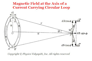
Magnetic Field at the Axis of a Current Carrying Circular Loop
Magnetic Field at the Axis of a Current-Carrying Circular Loop
Let us consider another current element of the same length at the bottom of the loop, directly opposite to the first element, which is at right angles to the plane of the page but directed inwards. the field due to $d\overrightarrow{B}$ but directed as shown in the figure above. It is clear that components of both the fields at right angles to the axis are equal and opposite. Hence they cancel each other. The component along the axis are in the same direction and so they are added up.

If we imagine the whole of the loop to be divided into such current elements, the resultant field $\overrightarrow{B}$ at $P$ is directed along the axis and its magnitude is given by

$B=\int dB \: \sin\phi$

Now substitute the value of $dB$ from equation $(1)$

$B=\int \frac{\mu_{\circ}}{4\pi} \frac{i \: dl}{r^{2}} \: \sin\phi$

From figure, $sin\phi=\frac{a}{r}$, we get

$dB=\int \frac{\mu_{\circ}}{4 \pi} \frac{i}{r^{2}} \frac{a}{r}dl$

$dB=\int \frac{\mu_{\circ}}{4 \pi} \frac{ia}{r^{3}} dl$

$dB= \frac{\mu_{\circ}}{4 \pi} \frac{ia}{r^{3}} \int dl$

$dB= \frac{\mu_{\circ}}{4 \pi} \frac{ia}{r^{3}} 2 \pi \: a \qquad \left( \int dl = 2 \pi \: a \right)$

$dB= \frac{\mu_{\circ}ia^{2}}{2r^{3}}$

Agian from figure $r^{2}=\left( a^{2} + x^{2}\right)^{3}$ or $r= \left( a^{2} + x^{2}\right)^{3/2}$. Now substitute the value of $r$ in above equation.

$B=\frac{\mu_{\circ}\: i\: a^{2}}{2(a^{2}+x^{2})^{3/2}}$

If it is a coil of $N$ turns, then each turn will contribute equally to $B$. Thus

$B=\frac{\mu_{\circ}\: N \: i \: a^{2}}{2(a^{2}+x^{2})^{3/2}}$

The direction of the magnetic field $\overrightarrow{B}$ is along the axis of the loop and that of the coil.

Magnetic field at the Centre of the Loop→

At the centre of the coil, we have $x=0$

$B=\frac{\mu_{\circ}\: N \: i}{2a}$

Again the direction of the magnetic field $\overrightarrow{B}$ is perpendicular to the plane of the coil i.e. Along the axis of the coil.

Popular Posts