Derivation of Einstein Coefficient Relation→
Let us consider the $N_{1}$ and $N_{2}$ is the mean population of lower energy state and upper energy state respectively. If the energy density of incident light is $\rho(\nu)$ then
The rate of transition of number of atoms due to absorption process:
$R_{abs}=B_{12} \: \rho(v) \: N_{1} \qquad(1)$
The above equation shows the number of atoms absorbing the photon per second per unit volume
Where $B_{12}$= Einstein Absorption Coefficent
The rate of transition of number of atoms due to sponteneous emission process:
$R_{sp}=A_{21} \: N_{2} \qquad(2)$
The above equation shows the number of atoms emitting the photon per second per unit volume due to spontaneous emission
Where $A_{21}$= Einstein Spontaneous Emission Coefficient
The rate of transition of the number of atoms due to stimulated emission process:
$R_{st}=B_{21} \: \rho(v) \: N_{2} \qquad(3)$
The above equation shows the number of atoms emitting the photon per second per unit volume due to stimulated emission
Where $B_{21}$= Einstein Stimulated Emission Coefficient
Under the thermal equilibrium, the mean population $N_{1}$ and $N_{2}$ in lower and upper energy states respectively must remain constant. This condition requires that the transition of the number of atoms from $E_{2}$ to $E_{1}$ must be equal to the transition of the number of atoms from $E_{1}$ to $E_{2}$. Thus
$\left.\begin{matrix}The \: number \: of \: atoms \: absorbing \\ photons \: per \: second \: per \: unit \: volume
\end{matrix}\right\} \\ = \left.\begin{matrix} The \: number \: of \: atoms \: emitting \\ photons \: per \: second \: per \: unit \: volume
\end{matrix}\right\}$
i.e $R_{abs}= R_{sp}+R_{st}$
$B_{12} \: \rho(v) \: N_{1}= A_{21} \: N_{2} + B_{21} \: \rho(v) \: N_{2}$
$B_{12} \: \rho(v) \: N_{1} - B_{21} \: \rho(v) \: N_{2} = A_{21} \: N_{2} $
$ \rho(v) (B_{12} \: N_{1} - B_{21} \: N_{2} ) = A_{21} \: N_{2} $
$\rho(v)=\frac{A_{21} \: N_{2}}{(B_{12} \: N_{1} - B_{21} \: N_{2} )} \qquad(4)$
We know that
$\frac{N_{1}}{N_{2}}=e^{\frac{(E_{2}-E_{1})}{kT}}$
$\frac{N_{1}}{N_{2}}=e^{\frac{h\nu}{kT}}$
Now substitute the value of $\frac{N_{1}}{N_{2}}$ in equation $(4)$
$\rho(v)=\frac{A_{21}}{B_{12}} \left [ \frac{1}{e^{\frac{h\nu}{kT}}- \frac{B_{21}}{B_{12}}} \right ] \qquad(5)$
According to Planck's Radiation Law
$\rho(v)=\frac{8\pi h \nu^{3}}{c^{3}} \left [ \frac{1}{e^{\frac{h\nu}{kT}}- 1} \right ] \qquad(6)$
Now comparing the equation $(5)$ and equation $(6)$
$\frac{B_{21}}{B_{12}}=1$ and $\frac{A_{21}}{B_{12}}=\frac{8\pi h \nu^{3}}{c^{3}}$
From the above equation, we get
$B_{21}=B_{12}$
$B_{12}=B_{21}=\frac{c^{3}}{8\pi h \nu^{3}}A_{21}$
Laser and properties of a Laser beam
Basic Definition of Laser→
LASER $\rightarrow$ Light Amplification by Stimulated Emission of Radiation.
Definition:
It is a device that produces a highly intense, monochromatic, collimated, and highly coherent light beam. Laser action mainly depends on the phenomenon of population inversion and stimulated emission.
The first successful Laser is a solid-state laser built by TH Maiman in 1960 using Ruby as an active medium.
Note→
The laser has often been referred to as an optical MASER because it operates in the visible spectrum portion of spectrum. In general, when the variation occurs below the infrared portion of the electromagnetic spectrum, the term MASER will be employed, and when stimulated emission occurs in the infrared, visible, or ultraviolet portion of the spectrum, the term laser or optical MASER will be used.
Properties of a Laser Beam→
The laser beam has the following main characteristics:
1.) A laser beam has high directionality and can be emitted only in one direction. The divergence of the laser beam can be less than $10^{-5}$ radian. Due to high directionality, these beams can be focused in very small areas.
2.) A laser beam is very narrow and hence can travel long distances without any spread. The spectral width ($\Delta \lambda$)of a laser beam is of the order of $10^{-6} A^{\circ}$.
3.) A laser beam is highly monochromatic. Its monochromaticity is much more than that of any conventional monochromatic source.
4.) The laser beam has high intensity and high power levels that can produce a temperature of the order of $10^{4} \: ^{\circ}C$.
5.) A laser beam has a high degree of coherence. It is highly temporally and spatially coherent.
Missing Order in double slit diffraction pattern
The equation for missing order in the double-slit diffraction pattern→
The nature of the diffraction pattern due to the double slits depends upon the relative values of $e$ and $d$. If, however, $e$ is kept constant and $d$ is varied, then certain orders of interference maxima will be missing.
We know that, the direction of interference maxima
$(e+d)\:sin\theta=\pm n\lambda \qquad(1)$
The direction of diffraction minima
$e \: sin\theta=\pm m\lambda \qquad(2)$
Divide the equation $(1)$ by equation $(2)$
$\frac{(e+d)}{e}=\frac{n}{m}$
Case (I)→
If $e=d$ then
n=2m
So for $m=1,2,3,....$
The $n=2,4,6,....$
Thus, the $2_{nd}, 4^{th}, 6^{th}, ...$ order interference maxima will be missing.
Case (II) →
If $e=\frac{d}{2}$ then
n=3m
So for $m=1,2,3,....$
The $n=3,6,9,....$
Thus, the $3_{rd}, 6^{th}, 9^{th}, ...$ order interference maxima will be missing.
Diffraction due to a plane diffraction grating or N- Parallel slits
A diffraction grating (or $N$-slits) consists of a large number of parallel slits of equal width and separated from each other by equal opaque spaces.
It may be constructed by ruling a large number of parallel and equidistance lines on a plane glass plate with the help of a diamond point. the duplicates of the original grating are prepared by pouring a thin layer of colloidal solution over it and then allowed to Harden. This layer is then removed from the original grating and fixed between two glass plates which serve as a plane transmission grating. Generally, A plane transmission grating has 10000 to 15000 lines per inch.
Theory→
Since plane diffraction grating is an $N$-slit arrangement, the deflection pattern due to it will be the combined diffraction effect of all such slits. Let a plane wavefront of monochromatic light be incident normally on the $N$-parallel slit of the gratings. Each point within the slits then sends out secondary wavelets in all directions.
Let $e$ be the width of each slipped and $d$ be the separation between any two consecutive slits then $(e+d)$ is known as the grating element. The diffracted ray from each slit, then $(e+d)$ is knowns as the grating element. The diffracted ray from each slit is focussed at a point $P$ on the screen $XY$ with the help of a convex lens $L$.
Expression for Intensity→
Let $S_{1}, S_{2}, S_{3},.......$ be the middle point of each slit and $S_{1}M_{1}, S_{2}M_{2}, S_{3}M_{3}, ........S_{N-1}M_{N-1}$ be the perpendicular drawn as shown in the figure.The waves diffracted from each slit are equivalent to a single wave amplitude:
$R=\frac{A\:sin\alpha}{\alpha} \qquad(1)$
The path difference between the waves from slit $S_{1}$ and $S_{2}$ is
$S_{2}M_{1}=(e+d)sin\theta$
The path difference between the waves from slit $S_{2}$ and $S_{3}$ is
$S_{3}M_{2}=(e+d)sin\theta$
The path difference between the waves from slit $S_{n-1}$ and $S_{n}$ is
$S_{N}M_{N-1}=(e+d)sin\theta$
Thus, it is obvious that the path difference between all the consecutive waves is the same and equal to $(e+d)sin\theta$
The corresponding phase difference
$\Delta \phi=\frac{2\pi}{\lambda}(e+d)sin\theta \qquad(2)$
Let $\Delta \phi=2\beta$
$\beta=\frac{\pi}{\lambda}(e+d)sin\theta \qquad(3)$
Thus, the resultant amplitude at $P$ is the resultant amplitude of $N$ waves, each of amplitude $R$ and its common phase difference is $(2\beta)$
$R'=\frac{R \: sin \left( \frac{2N\beta}{2} \right) }{sin \left( \frac{2\beta}{2} \right)} \qquad(4)$
The resultant amplitude at $P$
$R'=\frac{R \: sin N\beta}{sin \beta} $
Where $R=\frac{A\: sin\alpha}{\alpha}$. Now substitute the value of $R$ in the above equation and we get
$R'= \frac{A\: sin\alpha}{\alpha} \frac{ \: sin N\beta}{sin \beta} \qquad(5)$
The resultant intensity at $P$
$I=R'^{2}$
$I=\frac{A^{2} \: sin^{2} \alpha}{\alpha^{2}} \frac{ \: sin^{2} N\beta}{sin^{2} \beta} \qquad(6)$
The factor $\frac{A^{2} \: sin^{2} \alpha}{\alpha^{2}}$ gives the intensity pattern due to diffraction from a single slit while the factor $\frac{ \: sin^{2} N\beta}{sin^{2} \beta}$ gives the distribution of intensity due to interference from all the $N$-slit
Principle Maxima→
The intensity will be maximum when $sin\beta=0$ or $\beta=\pm n\pi$
Where $n=0,1,2,3,.....$
But under this condition, $sinN\beta$ is also equal to zero. Hence term $\frac{sin N\beta}{sin \beta}$ can be solve by
$\lim_{\beta \rightarrow \pm n\pi} \frac{ \: sin N\beta}{sin \beta}=\lim_{\beta \rightarrow \pm n\pi} \frac{\frac{d}{d\beta} (sin N\beta)}{\frac{d}{d\beta}(sin \beta)}$
$\lim_{\beta \rightarrow \pm n\pi} \frac{ \: sin N\beta}{sin \beta}=\lim_{\beta \rightarrow \pm n\pi} \frac{N cos N\beta}{cos \beta}$
$\lim_{\beta \rightarrow \pm n\pi} \frac{ \: sin N\beta}{sin \beta}=N \lim_{\beta \rightarrow \pm n\pi} \frac{ cos N\beta}{cos \beta}$
Where the value of $\lim_{\beta \rightarrow \pm n\pi} \frac{ cos N\beta}{cos \beta}=1$
$\lim_{\beta \rightarrow \pm n\pi} \frac{ \: sin N\beta}{sin \beta}=N \qquad(7)$
So the maximum intensity
$I=\frac{A^{2} \: sin^{2} \alpha}{\alpha^{2}} N^{2} \qquad(8)$
Thus, the condition for principle maxima
$sin \beta=0$
$\beta=\pm n\pi$
$(e+d)sin\theta=\pm n \lambda \qquad(9)$
For $n=0$, we get $\theta=0$ This $\theta=0$ gives the direction of zero-order principal maxima. For the value of $n=1,2,3,......$, gives the direction of first, second, third,....... order principal maxima.
Minima →
The intensity will be minimum, when $sin N\beta=0$ but $sin\beta=0$
$N\beta=\pm m\pi$
$N(e+d)sin\theta=\pm m \lambda \qquad(10)$
Where $m$ can take all integral values except $0, N,2N,3N,......$ because for these values of $m$, $sin\beta=0$ which gives the position of principal maxima.
Secondary maxima→
It is obvious from the above condition of minima, there are $(N-1)$ minima between two successive principal maxima. Hence, there are $(N-2)$ other maxima with alternative minima between two successive principal maxima. These $(N-2)$ maxima are called secondary maxima. To find the condition of secondary maxima equation $(6)$ is differentiated with respect to $\beta$ and equated to zero.
$\frac{dI}{d\beta}= \frac{A^{2}\:sin^{2}\alpha}{\alpha^{2}}2 \frac{sinN\beta}{sin\beta} \left [\frac{sin\beta . N. cosN\beta-sinN\beta . cos\beta}{sin^{2}\beta} \right ]$
$0= \frac{A^{2}\:sin^{2}\alpha}{\alpha^{2}}2 \frac{sinN\beta}{sin\beta} \left [\frac{sin\beta . N. cosN\beta-sinN\beta . cos\beta}{sin^{2}\beta} \right ]$
$N.sin\beta . cosN\beta - sinN \beta . cos\beta=0$
$\tan N\beta = N tan \beta \qquad(11)$
Now construct a right-angled triangle with the sides according to the above equation$(11)$
From the above triangle:
$sinN\beta=\frac{N tan\beta}{\sqrt{1+N^{2}tan^{2}\beta}} \qquad(12)$
Substituting the value of $sinN\beta$ from the above equation to equation (6)
$I=\frac{A^{2} \: sin^{2} \alpha}{\alpha^{2}} \frac{N^{2} tan^{2}\beta}{1+N^{2}tan^{2}\beta} \frac{ 1}{sin^{2} \beta}$
$I=\frac{A^{2} \: sin^{2} \alpha}{\alpha^{2}} \frac{N^{2}}{1+N^{2}tan^{2}\beta} \frac{ 1}{cos^{2} \beta} \qquad \left(\because tan\beta =\frac{sin\beta}{cos\beta} \right)$
$I=\frac{A^{2} \: sin^{2} \alpha}{\alpha^{2}} \frac{N^{2}}{cos^{2} \beta+N^{2}sin^{2}\beta} $
$I=\frac{A^{2} \: sin^{2} \alpha}{\alpha^{2}} \frac{N^{2}}{1- sin^{2} \beta+N^{2}sin^{2}\beta} $
$I=\frac{A^{2} \: sin^{2} \alpha}{\alpha^{2}} \frac{N^{2}}{1+(N^{2}-1) sin^{2} \beta} \qquad(12)$
Now divide the equation $(12)$ by equation $(8)$ so
$\frac{Intensity\: of\:secondary\:maxima}{Intensity\:of\:principal\:maxima}=\frac{1}{1+(N^{2}-1) sin^{2} \beta}$
It is obvious from the above equation that When $N$ increases then the intensity of secondary maxima decreases.
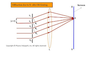 |
| Diffraction due to N- slits OR Grating |
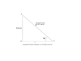 |
| Right-angled Triangle for Intensity Calculation |
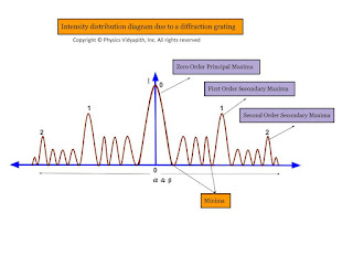 |
| Intensity distribution diagram due to a diffraction grating |
Fraunhofer diffraction due to a double slit
Let a plane wavefront be incident normally on slit $S_{1}$ and $S_{2}$ of equal $e$ and separated by an opaque distance $d$.The diffracted light is focused on the screen $XY$. The diffracted pattern on the screen consists of equally spaced bright and dark fringe due to interference of light from both the slits and modulated by diffraction pattern from individual slits.
op
The diffraction pattern due to double-slit can be explained considering the following points →
All the points in slits $S_{1}$ and $S_{2}$ will send secondary waves in all directions.
All the secondary waves moving along the incident wave will be focussed at $P$ and the diffracted waves will be focussed at $P'$
The amplitude at $P'$ is the resultant from two slit each of amplitude $R=\frac{A\:sin\alpha}{\alpha}$
T two waves from two-slit $S_{1}$ and $S_{2}$ will interfere at $P'$
Expression for Intensity →
$\Delta = S_{2}M$
$\Delta=(e+d)sin\theta\qquad(1)$
The corresponding phase difference →
$\Delta\phi= \frac{2\pi}{\lambda}(e+d)sin\theta \qquad(2)$
Let $\Delta \phi =2 \beta \qquad(3)$
$\beta=\frac{\pi}{\lambda}(e+d)sin\theta\qquad(4)$
The resultant amplitude at $P'$ can be obtained by the vector addition method. The resultant amplitude at $P'$
$R'^{2}=R^{2}+R^{2}+2R.R.cos\Delta\phi$
$R'^{2}=R^{2}+R^{2}+2R.R.cos2\beta \qquad \left( \because 2\beta=\Delta\phi \right)$
$R'^{2}=2R^{2}+2R^{2}cos2\beta$
$R'^{2}=2R^{2} \left( 1+cos2\beta \right)$
$R'^{2}=4R^{2} cos^{2}\beta \qquad(5)$
Where
$R$ - Resultant amplitude of each slit $S_{1}$
$R=\frac{A\: sin\alpha}{\alpha} \qquad(6)$
Substituting the value of $R$ in equation $(5)$
$R'^{2}=4 A^{2} \frac{sin^{2}\alpha}{\alpha^{2}} cos^{2} \beta \qquad(7)$
$R'=2 A \frac{sin\alpha}{\alpha} cos\beta \qquad(8)$
The intensity of the resultant diffraction pattern at $P'$
$I=4 A^{2} \frac{sin^{2}\alpha}{\alpha^{2}} cos^{2} \beta \qquad(9)$
Where $\alpha=\frac{\pi}{\lambda}e\:sin\theta \qquad(10)$
The resultant intensity at any point is the contribution of the following two factors →
The factor $\frac{A^{2}sin^{2}\alpha}{\alpha^{2}}$, represents the intensity distribution due to diffraction from any individual slits.
The factor $cos^{2}\beta$ represents the intensity distribution due to interference of waves from two parallel slits.
Condition for Maxima and Minima →
1. Maxima and minima due to diffraction term →
i.) Principal Maxima →
The diffraction term $\frac{A^{2}sin^{2}\alpha}{\alpha^{2}}$ gives the central maxima, for $\alpha=0$ so
$\frac{\pi}{\lambda}e\: sin\theta=0$
$sin\theta =0 $
$\theta=0$
ii.) Minima →
The diffraction term $\frac{A^{2}sin^{2}\alpha}{\alpha^{2}}$ gives the central minima, for $sin\alpha=0$ so
$\alpha=\pm m\pi$
$e\:sin\theta=\pm m\pi$
iii.) Secondary Maxima →
The secondary maxima are obtained in the direction given by →
$\alpha= \pm\frac{3\pi}{2},\pm\frac{5\pi}{2},\pm\frac{7\pi}{2},..............$
2. Maxima and minima due to interference term →
i.) Maxima→
The interference term $cos^{2}\beta$ gives maxima in the direction →
$cos^{2}=1$
$\beta=\pm n \pi$
$\frac{\pi}{\lambda}(e+d)sin\theta= \pm n \pi$
$(e+d)sin\theta= \pm n \lambda$
Where $n=0,1,2,3,.....$
In the direction $\theta=0^{\circ}$, the principle maxima due to interference and diffraction coincide.
ii.) Minima→
The interference term $cos^{2}\beta$ gives minima in the direction →
$cos^{2}\beta=0$
$\beta=\pm(2n+1)\frac{\pi}{2}$
$(e+d)sin\theta=\pm(2n+1)\frac{\pi}{2}$
The intensity distribution curve due to the diffraction term, interference term, and the combined effect is shown in the figure below →
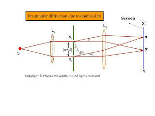 |
| Fraunhofer diffraction due to double slits |
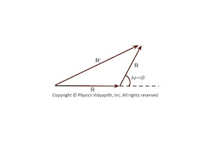 |
| Resultant Vector |
- Maxima and minima due to diffraction term
- Maxima and minima due to interference term
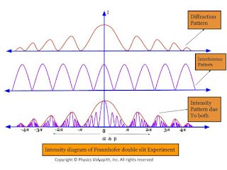 |
| Intensity diagram of Fraunhofer double slit Experiment |
Dispersive power of plane diffraction grating and its expression
Dispersive power of plane diffraction grating:
The dispersive power of a diffraction grating is defined as:
If the wavelenght changes from $\lambda$ to $\lambda +d\lambda$ and respective change in the angle of diffraction be from $\theta$ to $\theta+d\theta$ then the ratio $\left(\frac{d\theta}{d\lambda} \right)$
Expression of Dispersive power of a plane diffraction grating:
The grating equation for a plane transmission grating for normal incidence is given by
$(e+d)sin\theta=n\lambda \qquad(1)$
Where$(e+d)$ - Grating Element$\qquad \:\: \theta$ - Diffraction angle for spectrum of $n^{th}$ order
Differentiating equation $(1)$ with respect to $\lambda$, we have
$(e+d)cos\theta \left( \frac{d\theta}{d\lambda} \right)=n$
$\frac{d\theta}{d\lambda}=\frac{n}{(e+d)cos\theta}$
$\frac{d\theta}{d\lambda}=\frac{n}{(e+d)\sqrt{1-sin^{2}\theta}} \qquad(2)$
Now substitute the value of $sin\theta$ from equation$(1)$ in equation$(2)$
$\frac{d\theta}{d\lambda}=\frac{n}{(e+d)\sqrt{1- \frac{n^{2}\lambda^{2}}{(e+d)^{2}}}} $
$\frac{d\theta}{d\lambda}=\frac{1}{\sqrt{\left(\frac{e+d}{n} \right)^{2}}- \lambda^{2}}$
Here $d\theta$- Angular separation between two lines
The above equation gives the following conclusions:
The dispersive power is directly proportional to the order of spectrum$(n)$
The dispersive power is inversely proportional to the grating element $(e+d)$.
The dispersive power is inversely proportional to the $cos\theta$ i.e Larger value of $\theta$, higher is the dispersive power.
The rate of change of the angle of diffraction with the change in the wavelength of light are called dispersive power of plane grating.
Popular Posts
-
 Derivation→ Let us consider, The charge on a parallel-plate capacitor = $q$ The area of parallel-plate = $A$ The dis...
 -
 Derivation→ Let us consider, a current-carrying conductor $XY$ having length $l$ in which current $i$ is flowing from $X$ to $Y$. Now,...
 -
 A.) Electric field intensity at different points in the field due to the uniformly charged solid conducting sphere: Let us consider, A s...
 -
 Description: The motion of any particle is depends upon the force applying on it. In the magnetic field, the motion of charge is perp...
 -
Principle of Ruby Laser → Ruby laser is the first working laser that was invented by T.H.Maima in 1960. It is a three-level solid-stat...
-
 Derivation of electric field intensity due to the uniformly charged wire of infinite length: Let us consider a uniformly-charged (positi...
 -
 Electric Potential due to an Electric Dipole: The electric potential due to an electric dipole can be measured at different points: ...
 -
Prove that: Group velocity is equal to Particle Velocity Solution: We know that group velocity $V_{g}=\frac{d\omega}{dk}$ $V_{g}=...
-
 Alternating Current Circuit Containing Inductance only (L-Circuit): Let us consider, An alternating current circuit containing a coil of i...
 -
Gauss's Law: Gauss's law for electric flux is given by Carl Friedrich Gauss in 1813. He extended the work of Joseph-Louis Lagr...

