The equation for missing order in the double-slit diffraction pattern→
The nature of the diffraction pattern due to the double slits depends upon the relative values of $e$ and $d$. If, however, $e$ is kept constant and $d$ is varied, then certain orders of interference maxima will be missing.
We know that, the direction of interference maxima
$(e+d)\:sin\theta=\pm n\lambda \qquad(1)$
The direction of diffraction minima
$e \: sin\theta=\pm m\lambda \qquad(2)$
Divide the equation $(1)$ by equation $(2)$
$\frac{(e+d)}{e}=\frac{n}{m}$
Case (I)→
If $e=d$ then
n=2m
So for $m=1,2,3,....$
The $n=2,4,6,....$
Thus, the $2_{nd}, 4^{th}, 6^{th}, ...$ order interference maxima will be missing.
Case (II) →
If $e=\frac{d}{2}$ then
n=3m
So for $m=1,2,3,....$
The $n=3,6,9,....$
Thus, the $3_{rd}, 6^{th}, 9^{th}, ...$ order interference maxima will be missing.
Diffraction due to a plane diffraction grating or N- Parallel slits
A diffraction grating (or $N$-slits) consists of a large number of parallel slits of equal width and separated from each other by equal opaque spaces.
It may be constructed by ruling a large number of parallel and equidistance lines on a plane glass plate with the help of a diamond point. the duplicates of the original grating are prepared by pouring a thin layer of colloidal solution over it and then allowed to Harden. This layer is then removed from the original grating and fixed between two glass plates which serve as a plane transmission grating. Generally, A plane transmission grating has 10000 to 15000 lines per inch.
Theory→
Since plane diffraction grating is an $N$-slit arrangement, the deflection pattern due to it will be the combined diffraction effect of all such slits. Let a plane wavefront of monochromatic light be incident normally on the $N$-parallel slit of the gratings. Each point within the slits then sends out secondary wavelets in all directions.
Let $e$ be the width of each slipped and $d$ be the separation between any two consecutive slits then $(e+d)$ is known as the grating element. The diffracted ray from each slit, then $(e+d)$ is knowns as the grating element. The diffracted ray from each slit is focussed at a point $P$ on the screen $XY$ with the help of a convex lens $L$.
Expression for Intensity→
Let $S_{1}, S_{2}, S_{3},.......$ be the middle point of each slit and $S_{1}M_{1}, S_{2}M_{2}, S_{3}M_{3}, ........S_{N-1}M_{N-1}$ be the perpendicular drawn as shown in the figure.The waves diffracted from each slit are equivalent to a single wave amplitude:
$R=\frac{A\:sin\alpha}{\alpha} \qquad(1)$
The path difference between the waves from slit $S_{1}$ and $S_{2}$ is
$S_{2}M_{1}=(e+d)sin\theta$
The path difference between the waves from slit $S_{2}$ and $S_{3}$ is
$S_{3}M_{2}=(e+d)sin\theta$
The path difference between the waves from slit $S_{n-1}$ and $S_{n}$ is
$S_{N}M_{N-1}=(e+d)sin\theta$
Thus, it is obvious that the path difference between all the consecutive waves is the same and equal to $(e+d)sin\theta$
The corresponding phase difference
$\Delta \phi=\frac{2\pi}{\lambda}(e+d)sin\theta \qquad(2)$
Let $\Delta \phi=2\beta$
$\beta=\frac{\pi}{\lambda}(e+d)sin\theta \qquad(3)$
Thus, the resultant amplitude at $P$ is the resultant amplitude of $N$ waves, each of amplitude $R$ and its common phase difference is $(2\beta)$
$R'=\frac{R \: sin \left( \frac{2N\beta}{2} \right) }{sin \left( \frac{2\beta}{2} \right)} \qquad(4)$
The resultant amplitude at $P$
$R'=\frac{R \: sin N\beta}{sin \beta} $
Where $R=\frac{A\: sin\alpha}{\alpha}$. Now substitute the value of $R$ in the above equation and we get
$R'= \frac{A\: sin\alpha}{\alpha} \frac{ \: sin N\beta}{sin \beta} \qquad(5)$
The resultant intensity at $P$
$I=R'^{2}$
$I=\frac{A^{2} \: sin^{2} \alpha}{\alpha^{2}} \frac{ \: sin^{2} N\beta}{sin^{2} \beta} \qquad(6)$
The factor $\frac{A^{2} \: sin^{2} \alpha}{\alpha^{2}}$ gives the intensity pattern due to diffraction from a single slit while the factor $\frac{ \: sin^{2} N\beta}{sin^{2} \beta}$ gives the distribution of intensity due to interference from all the $N$-slit
Principle Maxima→
The intensity will be maximum when $sin\beta=0$ or $\beta=\pm n\pi$
Where $n=0,1,2,3,.....$
But under this condition, $sinN\beta$ is also equal to zero. Hence term $\frac{sin N\beta}{sin \beta}$ can be solve by
$\lim_{\beta \rightarrow \pm n\pi} \frac{ \: sin N\beta}{sin \beta}=\lim_{\beta \rightarrow \pm n\pi} \frac{\frac{d}{d\beta} (sin N\beta)}{\frac{d}{d\beta}(sin \beta)}$
$\lim_{\beta \rightarrow \pm n\pi} \frac{ \: sin N\beta}{sin \beta}=\lim_{\beta \rightarrow \pm n\pi} \frac{N cos N\beta}{cos \beta}$
$\lim_{\beta \rightarrow \pm n\pi} \frac{ \: sin N\beta}{sin \beta}=N \lim_{\beta \rightarrow \pm n\pi} \frac{ cos N\beta}{cos \beta}$
Where the value of $\lim_{\beta \rightarrow \pm n\pi} \frac{ cos N\beta}{cos \beta}=1$
$\lim_{\beta \rightarrow \pm n\pi} \frac{ \: sin N\beta}{sin \beta}=N \qquad(7)$
So the maximum intensity
$I=\frac{A^{2} \: sin^{2} \alpha}{\alpha^{2}} N^{2} \qquad(8)$
Thus, the condition for principle maxima
$sin \beta=0$
$\beta=\pm n\pi$
$(e+d)sin\theta=\pm n \lambda \qquad(9)$
For $n=0$, we get $\theta=0$ This $\theta=0$ gives the direction of zero-order principal maxima. For the value of $n=1,2,3,......$, gives the direction of first, second, third,....... order principal maxima.
Minima →
The intensity will be minimum, when $sin N\beta=0$ but $sin\beta=0$
$N\beta=\pm m\pi$
$N(e+d)sin\theta=\pm m \lambda \qquad(10)$
Where $m$ can take all integral values except $0, N,2N,3N,......$ because for these values of $m$, $sin\beta=0$ which gives the position of principal maxima.
Secondary maxima→
It is obvious from the above condition of minima, there are $(N-1)$ minima between two successive principal maxima. Hence, there are $(N-2)$ other maxima with alternative minima between two successive principal maxima. These $(N-2)$ maxima are called secondary maxima. To find the condition of secondary maxima equation $(6)$ is differentiated with respect to $\beta$ and equated to zero.
$\frac{dI}{d\beta}= \frac{A^{2}\:sin^{2}\alpha}{\alpha^{2}}2 \frac{sinN\beta}{sin\beta} \left [\frac{sin\beta . N. cosN\beta-sinN\beta . cos\beta}{sin^{2}\beta} \right ]$
$0= \frac{A^{2}\:sin^{2}\alpha}{\alpha^{2}}2 \frac{sinN\beta}{sin\beta} \left [\frac{sin\beta . N. cosN\beta-sinN\beta . cos\beta}{sin^{2}\beta} \right ]$
$N.sin\beta . cosN\beta - sinN \beta . cos\beta=0$
$\tan N\beta = N tan \beta \qquad(11)$
Now construct a right-angled triangle with the sides according to the above equation$(11)$
From the above triangle:
$sinN\beta=\frac{N tan\beta}{\sqrt{1+N^{2}tan^{2}\beta}} \qquad(12)$
Substituting the value of $sinN\beta$ from the above equation to equation (6)
$I=\frac{A^{2} \: sin^{2} \alpha}{\alpha^{2}} \frac{N^{2} tan^{2}\beta}{1+N^{2}tan^{2}\beta} \frac{ 1}{sin^{2} \beta}$
$I=\frac{A^{2} \: sin^{2} \alpha}{\alpha^{2}} \frac{N^{2}}{1+N^{2}tan^{2}\beta} \frac{ 1}{cos^{2} \beta} \qquad \left(\because tan\beta =\frac{sin\beta}{cos\beta} \right)$
$I=\frac{A^{2} \: sin^{2} \alpha}{\alpha^{2}} \frac{N^{2}}{cos^{2} \beta+N^{2}sin^{2}\beta} $
$I=\frac{A^{2} \: sin^{2} \alpha}{\alpha^{2}} \frac{N^{2}}{1- sin^{2} \beta+N^{2}sin^{2}\beta} $
$I=\frac{A^{2} \: sin^{2} \alpha}{\alpha^{2}} \frac{N^{2}}{1+(N^{2}-1) sin^{2} \beta} \qquad(12)$
Now divide the equation $(12)$ by equation $(8)$ so
$\frac{Intensity\: of\:secondary\:maxima}{Intensity\:of\:principal\:maxima}=\frac{1}{1+(N^{2}-1) sin^{2} \beta}$
It is obvious from the above equation that When $N$ increases then the intensity of secondary maxima decreases.
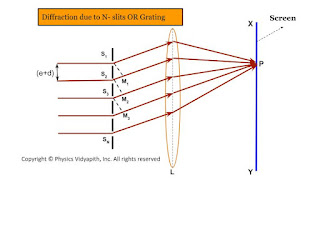 |
| Diffraction due to N- slits OR Grating |
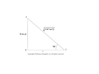 |
| Right-angled Triangle for Intensity Calculation |
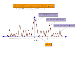 |
| Intensity distribution diagram due to a diffraction grating |
Fraunhofer diffraction due to a double slit
Let a plane wavefront be incident normally on slit $S_{1}$ and $S_{2}$ of equal $e$ and separated by an opaque distance $d$.The diffracted light is focused on the screen $XY$. The diffracted pattern on the screen consists of equally spaced bright and dark fringe due to interference of light from both the slits and modulated by diffraction pattern from individual slits.
op
The diffraction pattern due to double-slit can be explained considering the following points →
All the points in slits $S_{1}$ and $S_{2}$ will send secondary waves in all directions.
All the secondary waves moving along the incident wave will be focussed at $P$ and the diffracted waves will be focussed at $P'$
The amplitude at $P'$ is the resultant from two slit each of amplitude $R=\frac{A\:sin\alpha}{\alpha}$
T two waves from two-slit $S_{1}$ and $S_{2}$ will interfere at $P'$
Expression for Intensity →
$\Delta = S_{2}M$
$\Delta=(e+d)sin\theta\qquad(1)$
The corresponding phase difference →
$\Delta\phi= \frac{2\pi}{\lambda}(e+d)sin\theta \qquad(2)$
Let $\Delta \phi =2 \beta \qquad(3)$
$\beta=\frac{\pi}{\lambda}(e+d)sin\theta\qquad(4)$
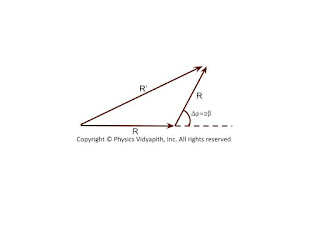
The resultant amplitude at $P'$ can be obtained by the vector addition method. The resultant amplitude at $P'$
$R'^{2}=R^{2}+R^{2}+2R.R.cos\Delta\phi$
$R'^{2}=R^{2}+R^{2}+2R.R.cos2\beta \qquad \left( \because 2\beta=\Delta\phi \right)$
$R'^{2}=2R^{2}+2R^{2}cos2\beta$
$R'^{2}=2R^{2} \left( 1+cos2\beta \right)$
$R'^{2}=4R^{2} cos^{2}\beta \qquad(5)$
Where
$R$ - Resultant amplitude of each slit $S_{1}$
$R=\frac{A\: sin\alpha}{\alpha} \qquad(6)$
Substituting the value of $R$ in equation $(5)$
$R'^{2}=4 A^{2} \frac{sin^{2}\alpha}{\alpha^{2}} cos^{2} \beta \qquad(7)$
$R'=2 A \frac{sin\alpha}{\alpha} cos\beta \qquad(8)$
The intensity of the resultant diffraction pattern at $P'$
$I=4 A^{2} \frac{sin^{2}\alpha}{\alpha^{2}} cos^{2} \beta \qquad(9)$
Where $\alpha=\frac{\pi}{\lambda}e\:sin\theta \qquad(10)$
The resultant intensity at any point is the contribution of the following two factors →
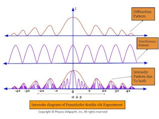
The factor $\frac{A^{2}sin^{2}\alpha}{\alpha^{2}}$, represents the intensity distribution due to diffraction from any individual slits.
The factor $cos^{2}\beta$ represents the intensity distribution due to interference of waves from two parallel slits.
Condition for Maxima and Minima →
1. Maxima and minima due to diffraction term →
i.) Principal Maxima →
The diffraction term $\frac{A^{2}sin^{2}\alpha}{\alpha^{2}}$ gives the central maxima, for $\alpha=0$ so
$\frac{\pi}{\lambda}e\: sin\theta=0$
$sin\theta =0 $
$\theta=0$
ii.) Minima →
The diffraction term $\frac{A^{2}sin^{2}\alpha}{\alpha^{2}}$ gives the central minima, for $sin\alpha=0$ so
$\alpha=\pm m\pi$
$e\:sin\theta=\pm m\pi$
iii.) Secondary Maxima →
The secondary maxima are obtained in the direction given by →
$\alpha= \pm\frac{3\pi}{2},\pm\frac{5\pi}{2},\pm\frac{7\pi}{2},..............$
2. Maxima and minima due to interference term →
i.) Maxima→
The interference term $cos^{2}\beta$ gives maxima in the direction →
$cos^{2}=1$
$\beta=\pm n \pi$
$\frac{\pi}{\lambda}(e+d)sin\theta= \pm n \pi$
$(e+d)sin\theta= \pm n \lambda$
Where $n=0,1,2,3,.....$
In the direction $\theta=0^{\circ}$, the principle maxima due to interference and diffraction coincide.
ii.) Minima→
The interference term $cos^{2}\beta$ gives minima in the direction →
$cos^{2}\beta=0$
$\beta=\pm(2n+1)\frac{\pi}{2}$
$(e+d)sin\theta=\pm(2n+1)\frac{\pi}{2}$
The intensity distribution curve due to the diffraction term, interference term, and the combined effect is shown in the figure below →
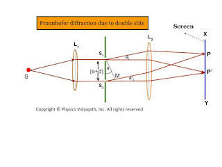 |
| Fraunhofer diffraction due to double slits |
 |
| Resultant Vector |
- Maxima and minima due to diffraction term
- Maxima and minima due to interference term
 |
| Intensity diagram of Fraunhofer double slit Experiment |
Dispersive power of plane diffraction grating and its expression
Dispersive power of plane diffraction grating:
The dispersive power of a diffraction grating is defined as:
If the wavelenght changes from $\lambda$ to $\lambda +d\lambda$ and respective change in the angle of diffraction be from $\theta$ to $\theta+d\theta$ then the ratio $\left(\frac{d\theta}{d\lambda} \right)$
Expression of Dispersive power of a plane diffraction grating:
The grating equation for a plane transmission grating for normal incidence is given by
$(e+d)sin\theta=n\lambda \qquad(1)$
Where$(e+d)$ - Grating Element$\qquad \:\: \theta$ - Diffraction angle for spectrum of $n^{th}$ order
Differentiating equation $(1)$ with respect to $\lambda$, we have
$(e+d)cos\theta \left( \frac{d\theta}{d\lambda} \right)=n$
$\frac{d\theta}{d\lambda}=\frac{n}{(e+d)cos\theta}$
$\frac{d\theta}{d\lambda}=\frac{n}{(e+d)\sqrt{1-sin^{2}\theta}} \qquad(2)$
Now substitute the value of $sin\theta$ from equation$(1)$ in equation$(2)$
$\frac{d\theta}{d\lambda}=\frac{n}{(e+d)\sqrt{1- \frac{n^{2}\lambda^{2}}{(e+d)^{2}}}} $
$\frac{d\theta}{d\lambda}=\frac{1}{\sqrt{\left(\frac{e+d}{n} \right)^{2}}- \lambda^{2}}$
Here $d\theta$- Angular separation between two lines
The above equation gives the following conclusions:
The dispersive power is directly proportional to the order of spectrum$(n)$
The dispersive power is inversely proportional to the grating element $(e+d)$.
The dispersive power is inversely proportional to the $cos\theta$ i.e Larger value of $\theta$, higher is the dispersive power.
The rate of change of the angle of diffraction with the change in the wavelength of light are called dispersive power of plane grating.
Fraunhofer diffraction due to a single slit
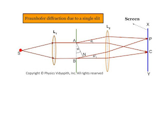
Let $S$ be a point monochromatic source of light of wavelength $\lambda$ placed at the focus of collimating lens $L_{1}$. The light beam is incident normally from $S$ on a narrow slit $AB$ of width $e$ and is diffracted from it. The diffracted beam is focused at the screen $XY$ by another converging lens $L_{2}$. The diffraction pattern having a central bright band followed by an alternative dark and bright band of decreasing intensity on both sides is obtained.
Analytical Explanation:
The light from the source $S$ is incident as a plane wavefront on the slit $AB$. According to Huygens's wave theory, every point in $AB$ sends out secondary waves in all directions. The undeviated ray from $AB$ is focused at $C$ on the screen by the lens $L_{2}$ while the rays diffracted through an angle $\theta$ are focussed at point $p$ on the screen. The rays from the ends $A$ and $B$ reach $C$ in the same phase and hence the intensity is maximum.
Expression for intensity:
To find the intensity at $P$, Let us draw normal $AN$ on $BN$. Therefore the path difference between the extreme rays is
$\Delta=BN$
$\Delta=AB \: sin \theta$
$\Delta=e \: sin \theta \qquad(1)$
Where $AB=e$ (width of the slit)
The phase difference
$\Delta \phi =\frac{2 \pi}{\lambda} e \: sin\theta \qquad(2)$ {from eq$(2)$}
Let AB be divided into a large number $n$ of equal parts then there may be an infinitely large number of the point sources of secondary wavelets between $A$ and $B$. The phase difference between any two consecutive parts is, therefore
$\frac{1}{n} \Delta \phi=\frac{1}{n} \frac{2 \pi}{\lambda} e \: sin\theta$
According to the theory of the composition of $n$ vibration each of amplitude $a$ and common phase difference $\delta$ between successive vibrations, the resultant amplitude at $P$ is given by
$R=a\frac{sin(\frac{n\delta}{2})}{sin(\frac{\delta}{2})} \qquad(4)$
Put the value of $\delta$ in equation $(4)$ so
$R=a \frac{sin [(\frac{1}{n} \frac{2\pi}{\lambda}e\: sin \theta) \frac{n}{2}]}{sin [\frac{1}{2}(\frac{1}{n} \frac{2\pi}{\lambda}e\: sin \theta)]}$
$R=a \frac{sin (\frac{\pi}{\lambda}e\: sin \theta)}{sin [\frac{1}{n} (\frac{\pi}{\lambda}e\: sin \theta)]} \qquad(5)$
Let $\alpha=\frac{\pi}{\lambda}e\: sin \theta \qquad(6)$
Then from equation $(5)$
$R=a \frac{sin \alpha }{sin (\frac{\alpha}{n})} \qquad(7)$
For the large value of $n$, the value of $\frac{\alpha}{n}$ is very small, Therefore $sin \alpha \approx \frac{\alpha}{n}$
Then equation $(7)$ can be written as
$R=a \frac{sin \alpha}{\frac{\alpha}{n}}$
$R=\frac{na \: sin\alpha}{\alpha}$
$R=\frac{A \: sin\alpha}{\alpha} \qquad(8)$
Where $A$ is total amplitude of $n$ vibration.$R$ is resultant amplitude of $n$ vibration
So the resultant intensity at $P$
$I=R^{2}$
$I=\frac{A^{2} \: sin^{2}\alpha}{\alpha^{2}} \qquad(9)$
Condition for Principle Maxima:
From equation $(7)$
$R=\frac{A \: sin\alpha}{\alpha}$
$R=\frac{A}{\alpha} [\alpha - \frac{\alpha^{3}}{3!} + \frac{\alpha^{5}}{5!} -\frac{\alpha^{7}}{7!} + ..... ]$
$R=A [1 - \frac{\alpha^{2}}{3!} + \frac{\alpha^{4}}{5!} -\frac{\alpha^{6}}{7!} + .....] $
If $\alpha=0$ then the resultant amplitude will be maximum then
$R=A$
And
$\frac{\pi}{\lambda}e\: sin \theta = 0$ {From equation $(6)$}
$sin \theta = 0$
$sin \theta = sin 0^{\circ}$
$ \theta = 0^{\circ}$
The resultant intensity at $P$ will be the maximum. For $\theta=0^{\circ}$ and called the principal maxima. Hence the intensity of the principal maxima:
$I_{0}=A^{2}$
Condition for Minima:
It is clear from equation $(8)$ that the intensity will be minimum when $sin\alpha=0$ but $\alpha \neq 0$ So.
$sin \alpha =0$
$sin \alpha= sin (m \pi)$
$\alpha=\pm m \pi$
And
$\frac{\pi}{\lambda}e\: sin \theta = \pm m \pi$ {From equation $(6)$}
$\frac{\pi}{\lambda}e\: sin \theta = \pm m \pi$
$ e\: sin \theta = \pm m \lambda$
The value of $m=1,2,3,4,5,......$ gives the direction of first, second, third,.....minima.
Condition for Secondary Maxima:
In the diffraction pattern, there are secondary maxima in addition to principal maxima. The condition of secondary maxima may be obtained by differentiating equation $(9)$ with respect to $\alpha$ and equating it to zero. Hence
$\frac{dI}{d\alpha}=\frac{d}{d\alpha} \left( A^{2} \frac{sin^{2}\alpha}{\alpha^{2}}\right)$
$\frac{dI}{d\alpha}=A^{2} 2 \left(\frac{sin\alpha}{\alpha} \left [\frac{\alpha \: cos\alpha - sin\alpha}{\alpha^{2}} \right ] \right)$
But for maxima $\frac{dI}{d\alpha}=0$
So $A^{2} 2 \left(\frac{sin\alpha}{\alpha} \left [\frac{\alpha \: cos\alpha - sin\alpha}{\alpha^{2}}\right ] \right)=0$
$ \frac{\alpha \: cos\alpha - sin\alpha}{\alpha^{2}}=0$
$\alpha \: cos\alpha - sin\alpha=0$
$\alpha=tan\alpha$
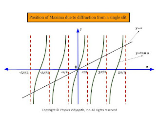
The above equation can be solved graphically by plotting the curves
$y=\alpha$
$y=tan\alpha$
The equation $y=\alpha$ gives the straight line passing through the origin and making an angle $45^{\circ}$ with the x-axis.
The point of intersection of these two curves gives the value of $\alpha$ satisfying the equation $\alpha=tan\alpha$. These points correspond to the value of
$\alpha= 0, \frac{\pm 3\pi}{2}, \frac{\pm 5\pi}{2}, \frac{\pm 7\pi}{2}, ................$
The first value $\alpha=0$ gives the position of principle maxima while the value of $\alpha= \frac{\pm 3\pi}{2}, \frac{\pm 5\pi}{2}, \frac{\pm 7\pi}{2}, ................$ gives the position first secondary maxima, second secondary maxima, and third secondary maxima and so on respectively.
The intensity of the first secondary maxima
$I_{1}=A^{2} \left [\frac{sin \left(\frac{3\pi}{2} \right)}{\frac{3\pi}{2}} \right ]^{2}$
$I_{1}=\frac{4}{9\pi^{2}}A^{2}=\frac{A^{2}}{22}=\frac{I_{0}}{22}$
Similarly, the intensities of secondary maxima
$I_{2}=A^{2} \left [\frac{sin \left(\frac{5\pi}{2} \right)}{\frac{5\pi}{2}} \right ]^{2}$
$I_{2}=\frac{4}{25\pi^{2}}A^{2}=\frac{A^{2}}{62}=\frac{I_{0}}{62}$
Thus, It is obvious from the value of $I_{0}, I_{1}, I_{2},.....$, etc that the diffraction pattern consists of a bright central maximum followed by minima of zero intensity and then secondary maxima of decreasing intensity on either side of it.
It is also obvious from the value of $I_{0}, I_{1}, I_{2},.....$, etc that the relative intensities of successive maxima are nearly
$I_{0}: I_{1}: I_{2}:...=1:\frac{4}{9\pi^{2}}: \frac{4}{25\pi^{2}}: \frac{4}{49\pi^{2}}:...$
 |
| Fraunhofer diffraction due to a single slit |
 |
| Position of maxima due to diffraction from a single slit |
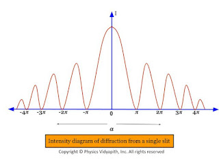 |
| Intensity diagram of diffraction from a single slit |
Interference of light and classification of Interference
Interference of light:
When two or more waves, having the same frequency and constant phase difference, travel simultaneously in the same region of a medium, these waves superimpose on each other and a resultant wave is obtained which has intensity at some points maximum and some points minimum in the region. This is phenomenon is known as interference of light.
When the intensity of the resultant wave is maximum in the region then this is called constructive interference.
when the intensity of the resultant wave is minimum in the region then this is called destructive interference.
Classification of Interference:
The phenomenon of interference may be grouped into two categories depending upon the formation of two coherent sources in practice.The interference of light is classified into two categories:
Division of amplitude
Division of wavefront
Division of amplitude:
In this method, the amplitude of the incident beam is divided into two or more parts are either by partial reflection or refraction. the beams travel in different paths, are superimposed on each other, and form the interference pattern.
Example:
Interference in the thin film, Newton's rings, and Michelson's interferometer are examples of two-beam interference and Fabry-Perot interferometer is the example of multiple-beam interference.
Division of Wavefront:
Under this category, the coherent sources are obtained by dividing the wavefront, originating from a common source, by employing mirrors, biprisms, or lenses. This class of interference requires initially a point source or a narrow slit source. The instruments used to obtain coherent sources and hence interference by division of wavefront are fresnel biprism fresnel Mila mirror Lloyd's mirror laser etc.
Popular Posts
-
 Derivation→ Let us consider, The charge on a parallel-plate capacitor = $q$ The area of parallel-plate = $A$ The dis...
 -
 A.) Electric field intensity at different points in the field due to the uniformly charged solid conducting sphere: Let us consider, A s...
 -
 Derivation→ Let us consider, a current-carrying conductor $XY$ having length $l$ in which current $i$ is flowing from $X$ to $Y$. Now,...
 -
Derivation of Einstein Coefficient Relation→ Let us consider the $N_{1}$ and $N_{2}$ is the mean population of lower energy state and upp...
-
 Alternating Current Circuit Containing Inductance only (L-Circuit): Let us consider, An alternating current circuit containing a coil of i...
 -
 Calculation of Motion of a body in a vertical Circle: Let us consider, A body that has mass $m$ moving in a vertical circle of radius $r$....
 -
 Alternating Current Circuit containing Resistance (R-Circuit): Let us consider, An alternating current circuit containing resistance $R$ on...
 -
A diffraction grating (or $N$-slits) consists of a large number of parallel slits of equal width and separated from each other by equal opaq...
-
 Description: The different series of hydrogen spectra can be explained by Bohr's theory. According to Bohr's theory, If the ioni...
 -
 Electric Dipole and Derivation of Electric field intensity at different points of an electric dipoleElectric Dipole: When two equal (i.e., equal in magnitude) and opposite-charge particles are placed at a very small distance apart, the ...
