Merits and Demerits of AC in Comparison to DC
(a) Merits
(i) Alternating current can be increased or decreased by using a transformer.
This is the reason that Alternating current can be transmitted from one place to other place at relatively lower expenditure and minimum loss of energy. In Direct current, it is not possible.
(ii) Alternating current can be controlled by choke coil or capacitor at very small loss of energy. To control Direct current resistance is required in which energy loss is very high.
(ii) Alternating current can easily be converted into Direct current by using a rectifier but converting Direct current into Alternating current is not easy.
(iv) Alternating current is cheaper than DC. (life of a cell or battery is very limited).
(b) Demerits
(i) Alternating current is more dangerous as compared to Direct current.
(ii) Alternating current cannot be used in electrolysis.
(iii) Most of the Alternating current of high frequency flows on the surface of the wire, therefore, a thick wire by joining number of thin insulated wires in parallel are to be used.
Power in Alternating Current Circuit
Definition of Power in Alternating Current Circuit:
The rate of power consumption in an alternating current circuit is known as power in the circuit.
Mathematical Analysis:
Let us consider an alternating current circuit in which the voltage and current at any instant are given by
$V=V_{\circ} sin \omega t \qquad(1)$
$i=i_{\circ} sin \left( \omega t - \phi \right) \qquad(2)$
Where $\phi$ $\rightarrow$ Phase difference between voltage and current
So instantaneous Power
$P=Vi$
$P=\left\{V_{\circ} sin \omega t \right\} \left\{ i_{\circ} sin \left( \omega t - \phi \right) \right\}$
$P=V_{\circ} i_{\circ} \: sin \omega t \: sin \left( \omega t - \phi \right)$
$P=\frac{V_{\circ} i_{\circ}}{2} \left[2\: sin \: \omega t \: sin \left( \omega t - \phi \right)\right]$
$P=\frac{V_{\circ} i_{\circ}}{2} \left[ cos \left( \omega t -\omega t + \phi \right) \\ \qquad - cos \left( \omega t + \omega t - \phi \right) \right]$
$P=\frac{V_{\circ} i_{\circ}}{2} \left[ cos \left(\phi \right) - cos \left( 2\omega t - \phi \right) \right]$
The average power for one cycle is:
$P_{avg}$ = The average value of $\left\{ \frac{V_{\circ} i_{\circ}}{2} \left[ cos \left(\phi \right) - cos \left( 2\omega t - \phi \right) \right] \right\}$
The term $cos \left( 2\omega t - \phi \right)$ is time-dependent and the average value of term $cos \left( 2\omega t - \phi \right)$ for complete one cycle is zero. So the average power dissipation in one cycle is
$P_{avg}= \frac{V_{\circ} i_{\circ}}{2} cos \phi $
$P_{avg}= \frac{V_{\circ}}{\sqrt{2}} \frac{i_{\circ}}{\sqrt{2}} cos \phi $
$P_{avg}= V_{rms} \: i_{rms} cos \phi $
Case -1 The circuit containing Pure Resistor only:
If the circuit contains a pure resistance only then voltage $V$ and current $i$ are always in the same phase. i.e. $\phi=0^{\circ}$ and $cos \phi = +1$, then average power
$P_{avg}= V_{rms} \: i_{rms} $
Case -2 The circuit containing Pure Inductor only:
If the circuit containing pure inductor only then voltage $V$ leads over current $i$ by $90^{\circ}$ i.e. $\phi=90^{\circ}$ and $cos 90^{\circ} = 0$, then average power
$P_{avg}= 0 $
Case -3 The circuit containing Pure Capacitor only:
If the circuit containing pure capacitor only then voltage $V$ lags behind current $i$ by $90^{\circ}$ i.e. $\phi=90^{\circ}$ and $cos 90^{\circ} = 0$, then average power
$P_{avg}= 0 $
Case -4 The circuit containing inductor and resistor only (L-R Circuit):
We know that the phase in the L-R circuit is
$tan \phi = \frac{X_{L}}{R}$
From the above equation, Draw the triangle as shown in the figure below:
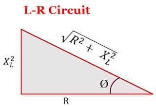 From the above figure, the value of $cos\phi$ is
$cos \phi = \frac{R}{\sqrt{R^{2} + X^{2}_{L}}}$
So average power
$P_{avg}= V_{rms} \: i_{rms} \frac{R}{\sqrt{R^{2} + X^{2}_{L}}} $
$\left(P_{avg}\right)_{L-R} \lt \left(P_{avg}\right)_{R}$
Thus, the average power consumption in an L-R circuit is less than the power consumed in a purely resistive circuit
Case -5 The circuit containing capacitor and resistor only (C-R Circuit):
We know that the phase in the C-R circuit is
$tan \phi = \frac{X_{C}}{R}$
From the above equation, Draw the triangle as shown in the figure below:
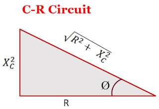 From the above figure, the value of $cos\phi$ is
$cos \phi = \frac{R}{\sqrt{R^{2} + X^{2}_{C}}}$
So average power
$P_{avg}= V_{rms} \: i_{rms} \frac{R}{\sqrt{R^{2} + X^{2}_{C}}} $
$\left(P_{avg}\right)_{C-R} \lt \left(P_{avg}\right)_{R}$
Thus, the average power consumption in a C-R circuit is less than the power consumed in a purely resistive circuit
Case -6 The circuit containing capacitor and inductor only (L-C Circuit):
We know that the phase in the L-R circuit is
$\phi = 90^{\circ}$ and $cos 90^{\circ} = 0$
So average power
$P_{avg}= 0 $
Case -7 The circuit containing inductor, capacitor, and resistor only (L-C-R Circuit):
We know that the phase in the L-C-R circuit is
$tan \phi = \frac{X_{L} - X_{C}}{R}$
From the above equation, Draw the triangle as shown in the figure below:
 From the above figure, the value of $cos\phi$ is
$cos \phi = \frac{R^{2}}{\sqrt{R^{2} + \left( X^{2}_{L} - X^{2}_{C} \right) }}$
So average power
$P_{avg}= V_{rms} \: i_{rms} \frac{R^{2}}{\sqrt{R^{2} + \left( X^{2}_{L} - X^{2}_{C} \right) }} $
$\left(P_{avg}\right)_{L-C-R} \lt \left(P_{avg}\right)_{R}$
Thus, the average power consumption in an L-C-R circuit is less than the power consumed in a purely resistive circuit
Wattless Current:
If the circuit contains only resistor or only inductor or only inductor and capacitor then power consumption in the circuit will be zero (i.e. there will be no energy dissipation in the circuit) due to the phase difference $90^{\circ}$ between voltage(or impedance) and current. So the current in the circuit is called the "Wattless current".


Self Induction Phenomenon and its Coefficient
Self Induction:
When a changing current flows in a coil then due to the change in magnetic flux in the coil produces an electro-motive force $\left(emf \right)$ in that coil. This phenomenon is called the principle of Self Induction.
The direction of electro-motive force can be found by applying "Lenz's Law".
Mathematical Analysis of Coefficient of Self Induction:
Let us consider that a coil having the number of turns is $N$. If the change in current is $i$, then linkage flux in a coil will be
 $N \phi \propto i$
$N\phi = L i \qquad(1)$
Where $L$ $\rightarrow$ Coefficient of Self Induction.
According to Faraday's law of electromagnetic induction. The electro-motive force $\left(emf \right)$ in a coil is
$e=-N\left( \frac{d \phi}{dt} \right)$
$e=-\frac{d \left(N \phi \right)}{dt} \qquad(2)$
From equation $(1)$ and equation $(2)$
$e=-\frac{d \left(L i\right)}{dt} $
$e=-L \left(\frac{d i}{dt} \right) $
$L = \frac{e}{\left(\frac{d i}{dt} \right)}$
If $\left(\frac{d i}{dt} \right) = 1$
Then
$L = e$
The above equation shows that If the rate of flow of current in a coil is unit then the coefficient of self-induction in that coil will be equal to the induced electro-motive force $\left( emf \right)$.

Mutual Induction Phenomenon and its Coefficient
Mutual Induction:
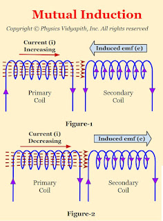
When two coils are placed near each other then the change in current in one coil ( Primary Coil) produces electro-motive force $\left( emf \right)$ in the adjacent coil ( i.e. secondary coil). This phenomenon is called the principle of Mutual Induction.
The direction of electro-motive force $\left( emf \right)$ depends or can be found by "Lenz's Law"
Mathematical Analysis of Coefficient of Mutual Induction:
Let us consider that two coils having the number of turns are $N_{1}$ and $N_{2}$. If these coils are placed near to each other and the change in current of the primary coil is $i_{1}$, then linkage flux in the secondary coil will be
 $N_{2}\phi_{2} \propto i_{1}$
$N_{2}\phi_{2} = M i_{1} \qquad(1)$
Where $M$ $\rightarrow$ Coefficient of Mutual Induction.
According to Faraday's law of electromagnetic induction. The electro-motive force $\left( emf \right)$ in the secondary coil is
$e_{2}=-N_{2}\left( \frac{d \phi_{2}}{dt} \right)$
$e_{2}=-\frac{d \left(N_{2} \phi_{2} \right)}{dt} \qquad(2)$
From equation $(1)$ and equation $(2)$
$e_{2}=-\frac{d \left(M i_{1} \right)}{dt} $
$e_{2}=-M \left(\frac{d i_{1}}{dt} \right) $
$M = \frac{e_{2}}{\left(\frac{d i_{1}}{dt} \right)}$
If $\left(\frac{d i_{1}}{dt} \right) = 1$
Then
$M = e_{2}$
The above equation shows that If the rate of flow of current in the primary coil is unit then the coefficient of mutual induction will be equal to the induced electro-motive force $\left( emf \right)$ in the secondary coil.

Faraday's laws of electromagnetic induction
Faraday's Laws of Electromagnetic Induction:
The Faraday's experiment shows the two laws which are known as Farday's laws of electromagnetic induction
First Law (Neumann's Law): The rate of change of magnetic flux through a circuit is equal to the emf produced in the circuit. This is also known as "Neumann Law"
$e=-\frac{\Delta \phi}{ \Delta t}$
Here negative sign shows the direction of emf.
If $\Delta t \rightarrow 0$
$e=-\frac{d \phi}{ d t}$
This equation represents an independent experimental law that cannot be derived from other experimental laws.
If the circuit is a tightly wound coil of $N$ turns, then the induced emf
$e=-N\frac{d \phi}{ d t}$
$e=-\frac{d \left(N \phi\right)}{ dt}$
Here $N \phi$ is called the 'Linkage magnetic flux'.
Note: The change in flux induces emf, not the current.
Second Law (Lenz's Law): The direction of induced EMF produced in a closed circuit is such that it opposes the original cause that produces it. It is also called "Lenz's law". The direction of induced EMF is described by Fleming's right-hand rule.
Popular Posts
-
 Derivation→ Let us consider, The charge on a parallel-plate capacitor = $q$ The area of parallel-plate = $A$ The dis...
 -
 Derivation→ Let us consider, a current-carrying conductor $XY$ having length $l$ in which current $i$ is flowing from $X$ to $Y$. Now,...
 -
 A.) Electric field intensity at different points in the field due to the uniformly charged solid conducting sphere: Let us consider, A s...
 -
 Calculation of Motion of a body in a vertical Circle: Let us consider, A body that has mass $m$ moving in a vertical circle of radius $r$....
 -
 Alternating Current Circuit containing Resistance (R-Circuit): Let us consider, An alternating current circuit containing resistance $R$ on...
 -
 Alternating Current Circuit Containing Inductance only (L-Circuit): Let us consider, An alternating current circuit containing a coil of i...
 -
Derivation→ Let us consider, The length of the conductor = $l$ The cross-section area of the conductor = $A$ The potential differe...
-
A diffraction grating (or $N$-slits) consists of a large number of parallel slits of equal width and separated from each other by equal opaq...
-
Prove that: Group velocity is equal to Particle Velocity Solution: We know that group velocity $V_{g}=\frac{d\omega}{dk}$ $V_{g}=...
-
Derivation of Einstein Coefficient Relation→ Let us consider the $N_{1}$ and $N_{2}$ is the mean population of lower energy state and upp...
