Principle construction and working of potentiometer

Potentiometer- An ideal voltmeter that does not change the original potential difference, needs to have infinite resistance. But a voltmeter cannot be designed to have infinite resistance. The potentiometer is one such instrument that does not draw any current from the circuit and still measures the potential difference. so it behaves as an ideal voltmeter.

"A potentiometer is an instrument. This is used to measure the potential difference between two points of an electric circuit and emf of a cell."

Principle- The principle of the potentiometer depends upon the potential gradient along the wire i.e. "When a constant current flows in a wire then the potential drops per unit length of the wire".

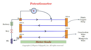
Construction- A potentiometer consists of a long wire $AB$ of uniform cross-section, usually, this wire is $4 m$ to $10 m$ long and it is made of the material having high resistivity and low-temperature coefficient such as manganin or constant. Usually, $1m$ long-separate pieces of wire are fixed on a wooden board. These pieces of wires are parallel to each other and joined in series by thick copper strips. A meter scale is used to measure the position of the jockey on the wire and it is fixed parallel to the wire ( As shown in the figure). The ends $A$ and $B$ are connected to a strong battery, a plug key $(K)$, and a rheostat $(Rh)$. The circuit is called a driving or auxiliary circuit that sends a constant current $i$ through the wire $AB$. Thus the potential gradually drops from $A$ to $B$. This potential drop is measured with the help of a jockey and voltmeter. A jockey is used to make point contact on the wire and it slides on the wire along the length of the wire.
Diagram of Potentiometer
Working- When a constant current flow through a wire of uniform cross-section area and composition, the potential drop across any length of the wire is directly proportional to that length.

If the voltmeter is connected between the end $A$ and Jockey $j$, it reads the potential difference $V$ across the length of the wire $AJ$. So according to ohm's law-

$V=iR$

$V=i \rho \frac{l}{A} \qquad(1)$

for a wire $\rho,i,A$ are constants. So

$\frac{i \: l}{A}=K (Constant)$

Hence equation $(1)$ can be written as

$V=Kl$

$V \propto l$

Metre Bridge OR Slide Wire Bridge

What is Metre Bridge?
It is the simplest practical application of the Wheatstone's bridge that is used to measure an unknown resistance.
Principle: Its working is based on the principle of Wheatstone's Bridge. When the Wheatstone's bridge is balanced

$\frac{P}{Q}=\frac{R}{S}$

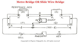
Construction: It consists of usually one-meter long manganin wire of uniform cross-section, stretched along a meter scale fixed over a wooden board and with its two ends soldered to two L-shaped thick copper strips $A$ and $C$. Between these two copper strips, another copper strip is fixed so as to provide two gaps $mn$ and $m_{1}n_{1}$. A resistance box (R.B.) is connected in the gap $mn$ and the unknown resistance $S$ is connected in the gap $m_{1}n_{1}$. A cell of emf $E$, Key $(K)$, and rheostat are connected across $AC$. A movable jockey and a galvanometer are connected across the $BD$, as shown in the figure.
Metre Bridge Setup
Metre Bridge Or Slide Wire Bridge

Working: In a Metre bridge, First take out the suitable resistance $R$ from the resistance box after that move the jockey along the wire $AC$ till there is not any deflection in the galvanometer. This is the condition of a balanced Wheatstone's bridge. If $P$ and $Q$ are the resistance of the part $AB$ and $BC$ of the wire, then for the balanced condition of the bridge, we have,

$\frac{P}{Q}=\frac{R}{S} \qquad(1)$

Let us consider:

The total length of the wire $AC=100 \: cm$
Length of the part $AB$ of wire = $l \: cm$
Length of the part $BC$ of wire = $(100-l) \: cm$
Resistance per unit length of the wire = $\sigma$
Resistance of wire of uniform cross-section = $\infty$

$\frac{P}{Q}=\frac{Resistance \: of \: AB}{Resistance \: of \: BC}$

$\frac{P}{Q}=\frac{\sigma l }{\sigma \left( 100-l \right) }$

$\frac{P}{Q}=\frac{ l }{ \left( 100-l \right) } \qquad (2)$

Now substitute the value of equation $(2)$ in equation $(1)$ then we get

$\frac{R}{S}=\frac{ l }{ \left( 100-l \right) } $

$S=\frac{R(100-l)}{l}$

Where

$S$ → Unknown Resistance
$R$ →Standard Resistance

Wheatstone's Bridge

It is an arrangement of four resistance used to determine one of this resistance quickly and accurately in terms of the remaining three resistance.

Objective: To find the unknown resistance with the help of the remaining three resistance.

Principle of Wheatstone Bridge: The principle of Wheatstone bridge is based on the principle of Kirchhoff's Law.

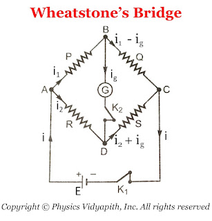
Construction: A Wheatstone bridge consists of four resistance $P$,$Q$,$R$, and $S$. This resistance is connected to form quadrilateral $ABCD$. A battery of EMF $E$ is connected between point $A$ and $C$ and a sensitive galvanometer is connected between point $B$ and $D$ Which is shown in the figure below.
Wheatstone's Bridge
Diagram of Wheatstone's Bridge
Working: To find the unknown resistance $S$, The resistance $R$ is to be adjusted like there is no deflection in the galvanometer. which means that there is not any flow of current in the arm $BD$. This condition is called "Balanced Wheatstone bridge" i.e

$\frac{P}{Q}=\frac{R}{S}$

Derivation of Balanced Condition of Wheatstone's Bridge: In accordance with Kirchhoff's first law, the currents through various branches are shown in the figure above.

For Close Loop $ABDA$

$0=P \: I_{1} - R \: I_{2} +G \: I_{g} \qquad(1)$

For Close Loop $CBDC$

$0=Q \left( I_{1} - I_{g} \right) -S \left( I_{2} + I_{g} \right) - G\: I_{g} \qquad(2)$

For Balanced Wheatstone Bridge: $I_{g}=0$

SO from equation $(1)$ and equation $(2)$

$0=P \: I_{1} - R \: I_{2} $

$P \: I_{1} = R \: I_{2} \qquad(3)$

$0=Q I_{1} -S I_{2}$

$Q I_{1} = S I_{2} \qquad(4)$

Now divide the equation $(4)$ and equation $(3)$, then we get

$\frac{P}{Q}=\frac{R}{S}$

Kirchhoff's laws for an electric circuits

Kirchhoff's laws: Kirchhoff had given two laws for electric circuits i.e.
  1. Kirchhoff's Current Law or Junction Law

  2. Kirchhoff's Voltage Law or Loop Law
  1. Kirchhoff's Current Law or Junction Law: Kirchhoff's current law state that

    The algebraic sum of all the currents at the junction in any electric circuit is always zero.

    $\sum_{1}^{n}{i_{n}}=0$

    Sign Connection: While applying the KCL, the current moving toward the junction is taken as positive while the current moving away from the junction is taken as negative.
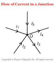
    Flow of Current in a Junction
    The flow of Current in a junction
    So from figure,the current $i_{1}$,$i_{2}$,$i_{5}$ is going toward the junction and the current $i_{3}$,$i_{4}$, So

    $\sum{i}= i_{1}+i_{2}+(-i_{3})+(-i_{4})+i_{5}$

    According to KCL $\sum{i}= 0$, Now the above equation can be written as

    $i_{1}+i_{2}+(-i_{3})+(-i_{4})+i_{5}=0 \qquad$

    $i_{1}+i_{2}+i_{5}=i_{3}+i_{4}$

    Thus, the sum of current going towards the junction is equal to the sum of current going away from the junction.

    In other words, at any junction, neither the charge accumulates nor the charge is removed. So this law represents conservation of charge.


  2. Kirchhoff's Voltage Law or Loop Law: Kirchhoff's voltage law state that:

    The algebraic sum of all the voltage or emf in any closed loop of an electric circuit is always zero.

    $\sum_{1}^{n}{E_{n}}=0$

    This means that the algebraic sum of all the emf applied in any closed loop is always equal to the algebraic sum of the product of current and resistance in the closed loop.

    $\sum{E}=\sum {i.R}$

    Sign Connection: While applying this law, a product of current and resistance is taken as positive when we traverse in the direction of the conventional current and the emf is taken positively when we traverse from negative to the positive electrode through the electrolyte.
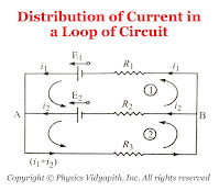
    Distribution of current in a loop of circuit
    Distribution of Current in a Loop of Circuit
    So from the figure:

    For Mesh $(1)$

    $E_{1}-E_{2}=i_{1}R_{1}-i_{2}R_{2} \qquad(1)$

    For Mesh $(2)$

    $E_{2}=i_{2}R_{2}+\left( i_{1}+i_{2} \right)R_{3} \qquad(2)$

Displacement Current

Description of Displacement Current: The concept of displacement current was first introduced by Maxwell purely on the theoretical ground.

Maxwell postulates that "It is not only current in a conductor that produces a magnetic field but a changing electric field (or time varying electric field) in vacuum or in dielectric also produces the magnetic field. It means that a changing electric field is equivalent to a current which flows as long as the electric field is changing. This equivalent current in a vacuum or dielectric produces the same magnetic effect as an ordinary or conductor current in a conductor. This equivalent current is known as displacement current".

According to the Maxwell modified ampere's law.

$\oint \overrightarrow{B}. \overrightarrow{dl}= \mu_{\circ}i+\mu_{\circ}i_{d}$

Where $i_{d}$ = Displacement Current

Mechanism of Flow of Charge in Metals: Free Electron Gas Theory

Theory of Free Electron Gas Model → According to the electron gas theory

1. The free electrons are continuous in motion inside the metal. The motion of free electrons are random inside the metal.

2. When the free electrons are collisied to each other then the direction of electrons are changed.

3. Mean free Path: The length covered by free electrons, between the two successive collisions is called the "Mean Free Path".

4. Relaxation Time: The time taken between the two successive collisions of free electrons is called the Relaxation time. It is represented by $\tau$.

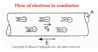
5. Drift velocity: When a potential is applied across the metal then these electrons do not move own velocity but it move with an average velocity in the opposite direction of the electric field. This average velocity is called the "Drift Velocity". The drift velocity of electrons depends upon the applied potential.

6. Mobility of Electrons: When a potential $V$ is applied across the metal then electrostatic force $F$ acts on the electrons i.e

$F=qE $

$F=NeE \qquad(1)$

Where
$N$ →The number of free electrons inside the metal
$E$ → The electric field due to the applied potential

When this electrostatic force is applied to the electrons then these electrons are accelerated with accelerated $a$ i.e

$F=ma \qquad(2)$

From equation $(1)$ and equation $(2)$ we can write

$ma=N\:e\:E$

$a=\frac{N}{m}eE$

$\frac{v_{d}}{\tau}=\frac{N}{m}eE \qquad \left( \because a=\frac{v_{d}}{\tau} \right)$

$v_{d}=\frac{Ne\tau}{m} E$

$v_{d}=\mu E$

Where $\mu=\frac{Ne\tau}{m}$. It is known as the mobility of electrons.

Derivation of Ohm's Law

Derivation→

Let us consider,

The length of the conductor = $l$
The cross-section area of the conductor = $A$
The potential difference across the conductor = $V$
The drift velocity of an electron in conductor = $v_{d}$

Now from the equation of the mobility of electron i.e.

$v_{d}= \mu E$

$v_{d}= \left( \frac{e\tau}{m} \right) E \qquad \left(\because \tau = \frac{e\tau}{m} \right)$

$v_{d}= \left( \frac{e\tau}{m} \right) \frac{V}{l}\qquad (1) \qquad \left(\because E = \frac{V}{l} \right)$

Now from the equation of drift velocity and electric current

$i=neAv_{d}$

Now substitute the value of $v_{d}$ from equation $(1)$ to above equation

$i=neA\left( \frac{e\tau}{m} \right) \frac{V}{l}$

$i=\left( \frac{ne^{2}A\tau}{ml} \right)V$

$\frac{V}{i}=\left( \frac{ml}{ne^{2}A\tau} \right)$

$\frac{V}{i}=R$

Where $R = \frac{ml}{ne^{2}A\tau} $ is known as electrical resistance of the conductor.

Thus

$V=iR$

This is Ohm's Law.

Relation between electric current and drift velocity

Derivation→ Let us consider

  • The length of the conductor = $l$

  • The cross-section area of the conductor = $A$

  • The total number of free electrons inside the conductor = $N$

  • The current flow in the conductor = $i$

  • Flow of electrons in conductor
    The flow of Electron in Conductor
  • The Relaxation time between the two successive collisions =$\tau$
  • According to the law of current density

    $J=\frac{i} {A} $

    $J=\frac{q} {A \tau} \qquad \left( \because i=\frac{q}{\tau} \right)$

    $J=\frac{N \: e }{A \tau} \qquad \left( \because q=Ne \right)$

    Now multiply by length of conductor $l$ in above equation. Therefore we get

    $J=\frac{N \: e \: l}{A \tau\: l} $

    $J=\frac{N \: e \: l}{V \tau\: }\qquad \left(\because V=A.l \right)$

    Where $V$ is volume of the conductor.

    $J=\frac{n \: e \: l}{ \tau }\qquad \left( \because n=\frac{N}{V} \right)$

    Where $n$ is total number of electrons per unit .

    $J=n \: e \: v_{d}\qquad \left( \because v_{d}=\frac{l}{\tau}\right)$

    Where $v_{d}$ are known as drift velocity of charged particles.

    Now substitute the value of current density $J$ from equation $(1)$ to above equation then above equation can be written as

    $i=neAv_{d}$

    Energy Stored in a Charged Capacitor

    Description→

    When a capacitor is charged, the work is done by charged battery (i.e the chemical energy of the battery is used to charge the capacitor). As the capacitor gets charged, the potential difference between its plates increases. Due to this increase in the potential difference between the plates, the battery has to give the same amount of charge to the capacitor. Because of that, the battery has to do more and more work.

    The total amount of work done in charging the capacitor is stored in the form of electric potential energy in between the capacitor plates. This energy is retrieved as heat when the capacitor is discharged through a resistance.

    Derivation→

    Let us consider, a capacitor of capacitance $C$with a potential difference of $V$ between the plates.

    In the process of charging, electrons are transferred from the positive to negative, unit each plate acquires an amount of charge $q$. Suppose during the process of charging, we increase the charge from $q'$ to $q'+dq'$ by transferring an amount of negative charge $dq'$ from the positive to the negative plate. the work done

    $dw=V' \: dq'$

    $dw=\frac{q'}{C} \: dq'$

    Therefore, the total work done in charging the capacitor from the uncharged state (i.e. zero charge in the capacitor) to the final charge $q$ will be

    $W=\int_{0}^{W} dw$

    $W=\int_{0}^{q} \frac{q'}{C} \: dq'$

    $W=\frac{1}{2}\left[ \frac{q'^{2}}{C} \right]^{q}_{0} $

    $W=\frac{1}{2}\left[ \frac{q^{2}}{C} \right]$

    $W=\frac{1}{2}\:C \: V^{2}$

    This work done is stored in the form of potential energy $U$ within the capacitor. Thus

    $U=\frac{1}{2}\:C \: V^{2} $

    $U=\frac{1}{2}\frac{q^{2}}{C}$

    Energy Stored in Combination of Capacitor→

    If many capacitors are combined in series, or in parallel, the total potential energy stored in either combination is equal to the sum of the potential energies stored in the individual capacitor. This follows from the combination of the capacitor's expressions:

    The potential energy is stored in a series combination→

    The potential energy stored in a series combination (here $q$ is constant) is

    $U=\frac{1}{2}\frac{q^{2}}{C}$

    For series combination the capacitance of capacitor i.e. $\frac{1}{C}=\frac{1}{C_{1}}+\frac{1}{C_{2}}+\frac{1}{C_{2}}+..........$. Now substitute the value of $\frac{1}{C}$ in above equation

    $U=\frac{1}{2}q^{2} \frac{1}{C_{1}}+\frac{1}{C_{2}}+\frac{1}{C_{2}}+.......... $

    $U= \left( \frac{1}{2}q^{2} \frac{1}{C_{1}}+\frac{1}{2}q^{2} \frac{1}{C_{2}}+ \frac{1}{2}q^{2} \frac{1}{C_{2}}+.......... \right)$

    $U=U_{1}+U_{2}+U_{3}+.........$

    The potential energy is stored in a parallel combination→

    The potential energy is stored in a parallel combination (here $V$ is constant) is

    $U=\frac{1}{2}CV^{2}$

    For parallel combination the capacitance of capacitor i.e. $C=C_{1}+C_{2}+C_{3}+......$. Now substitute the value of $C$ in the above equation

    $U=\frac{1}{2} \left( C_{1}+C_{2}+C_{3}+........... \right) V^{2}$

    $U= \frac{1}{2} C_{1} V^{2} + \frac{1}{2} C_{2} V^{2} +\frac{1}{2} C_{3}V^{2} +..... $

    $U=U_{1}+U_{2}+U_{3}+......$
    Force between the plates of a Charged Parallel Plate Capacitor

    Derivation and Description→

    Consider, A parallel plate capacitor with a charge $+q$ on one of its plates and $-q$ on the other plate. Let initially the plates of the capacitor are almost, but not quite touching. Due to opposite polarity, there is an attractive force $F$ between the plates. Now If these plates are gradually pulling and apart to a distance $d$, in such a way that $d$ is still small compared to the linear dimension of the plates, then the approximation of a uniform field between the plates is maintained and thus the force remains constant.
    Force between the charged Parallel Plates of Capacitor
    The force between the charged parallel plates of the capacitor
    Now the work done in separating the plates from near $0$ to $d$,

    $W=F.d \qquad(1)$

    This work done $(W)$ is stored as electrostatic potential energy $(U)$ between the plates, i.e.

    $U=\frac{1}{2}q V $

    But $V=E.d$, then the above equation can be written as

    $U=\frac{1}{2}q \: E \: d \qquad(2)$

    But the equation $(1)$ and equation $(2)$ both are equal then

    $F.d=\frac{1}{2}q \: E \: d$

    $ F=\frac{1}{2}q \: E $

    The factor $\frac{1}{2}$ arises because just outside the conducting plates the field is $E$ and inside the plates, the field is zero. So the average value $\frac{E}{2}$ contributes to the force.

    Popular Posts

    Study-Material


  • Classical world and Quantum world

  • Inadequacy of classical mechanics

  • Drawbacks of Old Quantum Theory

  • Bohr's Quantization Condition

  • Energy distribution spectrum of black body radiation

  • Energy distribution laws of black body radiation

  • The Compton Effect | Experiment Setup | Theory | Theoretical Expression | Limitation | Recoil Electron

  • Davisson and Germer's Experiment and Verification of the de-Broglie Relation

  • Significance of Compton's Effect

  • Assumptions of Planck’s Radiation Law

  • Derivation of Planck's Radiation Law

  • de-Broglie Concept of Matter wave

  • Definition and derivation of the phase velocity and group velocity of wave

  • Relation between group velocity and phase velocity ($V_{g}=V_{p}-\lambda \frac{dV_{p}}{d\lambda }$)

  • Group velocity is equal to particle velocity($V_{g}=v$)

  • Product of phase velocity and group velocity is equal to square of speed of light ($V_{p}.V_{g}=c^{2}$)

  • Heisenberg uncertainty principle

  • Generation of wave function for a free particle

  • Physical interpretation of the wave function

  • Derivation of time dependent Schrodinger wave equation

  • Derivation of time independent Schrodinger wave equation

  • Eigen Function, Eigen Values and Eigen Vectors

  • Postulate of wave mechanics or Quantum Mechanics

  • Quantum Mechanical Operators

  • Normalized and Orthogonal wave function

  • Particle in one dimensional box (Infinite Potential Well)

  • Minimum Energy Or Zero Point Energy of a Particle in an one dimensional potential box or Infinite Well

  • Normalization of the wave function of a particle in one dimension box or infinite potential well

  • Orthogonality of the wave functions of a particle in one dimension box or infinite potential well

  • Eigen value of the momentum of a particle in one dimension box or infinite potential well

  • Schrodinger's equation for the complex conjugate waves function

  • Probability Current Density for a free particle in Quantum Mechanics

  • Ehrenfest's Theorem and Derivation

  • Momentum wave function for a free particle

  • Wave function of a particle in free state

  • One dimensional Step Potential Barrier for a Particle


  • Blog Archive