Relation between angular velocity and linear velocity

Mathematical Relation between angular velocity $(\omega)$ and linear velocity$(v)$:
Relation between angular  velocity (v) and linear velocity (⍵)
We know that the angular displacement of the particle is

$\Delta \theta= \frac{\Delta s}{r} \qquad(1)$

Where $r$ = The radius of a circle.

Now divide by $\Delta t$ on both side of equation $(1)$

$\frac{\Delta \theta}{\Delta t}=\frac{1}{r} \frac{\Delta s}{\Delta t} $

If $\Delta t \rightarrow 0$, then the above equation can be written as

$\underset{\Delta t \rightarrow 0}{Lim}\: \frac{\Delta \theta}{\Delta t}=\frac{1}{r}\: \underset{\Delta t \rightarrow 0}{Lim} \: \frac{\Delta s}{\Delta t} \qquad(2)$

Where
$\underset{\Delta t \rightarrow 0}{Lim}\: \frac{\Delta \theta}{\Delta t}$ = Instantaneous Angular Velocity $(\omega)$

$\underset{\Delta t \rightarrow 0}{Lim} \: \frac{\Delta s}{\Delta t}$= Instantaneous Linear Velocity $(v)$

Now equation $(2)$ can be written as

$\omega=\frac{1}{r}v$

$v=r\omega$

The above equation shows that linear or tangential velocity depends on the angular velocity and radius of the circular path. This means that if the radius of the circular path increases with the same angular velocity, then the linear velocity will also increase.

Conservation's Law of linear momentum and its Derivation

Derivation of Conservation's law of Linear momentum from Newton's Second Law and Statement: Let us consider, A particle that has mass $m$ and is moving with velocity $v$ then According to Newton's second law the applied force on a particle is

Derivation From General Form Derivation from Differential Form
$F=ma$

$F=m \frac{\Delta v}{\Delta t}$

$F= \frac{\Delta (mv)}{\Delta t}$

$F= \frac{\Delta P}{\Delta t} \qquad \left( \because P=mv \right)$

If the applied force on a body is zero then

$\frac{\Delta P}{\Delta t}=0$

$\Delta P=0$

Here $\Delta P$ is change in momentum
of the particle .i.e

$P_{2}-P_{1}=0$

$P_{2}=P_{1}$

$P=Constant$
$F=ma$

$F=m \frac{dv}{dt}$

$F= \frac{dmv}{dt}$

$F= \frac{dP}{dt} \qquad \left( \because P=mv \right)$

If the applied force on a body is zero then

$\frac{dP}{dt}=0$

$dP=0$

On integrating the above equation

$P=constant$
From the above equation, we conclude the statement i.e.
When no external force is applied to a particle, the total momentum of a particle is always conserved.

Derivation of Conservation's law of Linear momentum from Newton's Third Law and Statement: Let us consider, The two-particle that have mass $m_{1}$ and $m_{2}$ are moving towards each other. If
Conservation's Law of Linear Momentum From Newton’s Third Law
The velocity of the particles $m_{1}$ before collision is = $u_{1}$

The velocity of the particles $m_{2}$ before collision is = $u_{2}$

The velocity of the particles $m_{1}$ after collision is = $v_{1}$

The velocity of the particles $m_{2}$ after the collision is = $v_{2}$

When these particles collide to each other than according to Newton's third law

$F_{12}=-F_{21}$

$m_{1}a_{1}=m_{2}a_{2}$

$m_{1}\frac{\Delta V_{1}}{\Delta t}=m_{2} \frac{\Delta V_{2}}{\Delta t} \quad (1) \qquad \left(\because a=\frac{\Delta V} {\Delta t} \right)$

Where
$\Delta V_{1}$= Change in Velocity of mass $m_{1}$ i.e $\left( v_{1}-u_{1} \right)$
$\Delta V_{2}$= Change in Velocity of mass $m_{2}$ i.e $\left( v_{2}-u_{2} \right)$

So from equation $(1)$

$m_{1}\frac{\left( v_{1}-u_{1} \right)}{\Delta t}=m_{2} \frac{\left( v_{2}-u_{2} \right)}{\Delta t}$

$m_{1}\left( v_{1}-u_{1} \right)=m_{2} \left( v_{2}-u_{2} \right)$

$m_{1} v_{1}- m_{1} u_{1}=m_{2}v_{2}- m_{2} u_{2}$

$m_{1} u_{1}+ m_{2} u_{2}=m_{1}v_{1} + m_{2} v_{2}$

From the above equation, we conclude the statement i.e.

When two particle collide two each other. If the total momentum of the particles before the collision and total momentum of the particles after is collision is same then it is known as conservation law of linear momentum.

Alternating Current Circuit containing Capacitance only (C-Circuit)

Alternating Current Circuit Containing Capacitance Only (C-Circuit): Let us consider, A circuit containing a capacitor of capacitance $C$ only which is connected with an alternating EMF i.e electromotive force source i.e.
Alternating Current Circuit Containing Capacitance only
Let us consider, A circuit containing a coil of inductance $L$ only which is connected with an alternating EMF i.e electromotive force source i.e.

$E=E_{\circ}sin\omega t\qquad(1)$

When alternating emf is applied across the capacitor plates then the charge on capacitor plates varies continuously and correspondingly current flows in the connecting leads. Let the charge on the capacitor plates is $q$ and the current in the circuit at any instant is $i$. Since there is no resistance in the circuit then the instantaneous potential difference is $\frac{q}{C}$ across the capacitor plates must be equal to the applied emf i.e.

$\frac{q}{C} = E_{\circ} sin \omega t$

$q = CE_{\circ} sin \omega t \qquad(2)$

The instantaneous current $i$ in the circuit is, therefore

$i=\frac{dq}{dt} \qquad(3)$

Now substitute the value of $q$ from equation $(2)$ to equation $(3)$

$i=\frac{d}{dt} CE_{\circ} sin \omega t $

$i=CE_{\circ} \omega cos\omega t$

$i=\omega CE_{\circ} cos\omega t$

$i=\frac{E_{\circ}}{\frac{1}{\omega C}} cos\omega t$

$i=\frac{E_{\circ}}{X_{C}} cos\omega t$

Where $X_{C}= \frac{1}{\omega C}$ is known as capacitive reactance.

$i=i_{\circ} cos\omega t \qquad(4)$

Where the $i_{\circ}=\frac{E_{\circ}}{X_{C}}$ is the maximum current in the circuit. Now apply Ohm's law in this equation and we find that the term $X_{C}=\frac{1}{\omega C}$ has the dimension of resistance. It represents the 'effective opposition' of the capacitor to the flow of alternating current. It is known as the 'reactance of the capacitor' or 'capacitive reactance' and is denoted by $X_{C}$. The capacitive reactance is infinite for DC for which $f=0$.

$i=i_{\circ} sin \left( \omega t + \frac{\pi}{2} \right) \qquad(4)$

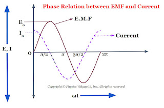
Now compare equation $(1)$ and equation $(4)$ which shows that an alternating circuit containing a capacitor only, the current leads the emf by a phase angle of $\frac{\pi}{2}$ or $90^\circ$ (or the emf lags behind the current by a phase angle of $\frac{\pi}{2}$). The phase diagram between EMF and the current of a capacitor is shown below-
Phase Relation between EMF and Current of a Capacitor
The phasor diagram between the EMF and current of a capacitor is also shown in the given figure below-
Phasor Diagram between EMF and Current of a capacitor

Alternating Current Circuit containing Inductance only (L-Circuit)

Alternating Current Circuit Containing Inductance only (L-Circuit): Let us consider, An alternating current circuit containing a coil of inductance $L$ only. This inductor is connected with an alternating EMF i.e electromotive force source i.e.
Alternating Current Circuit Containing Inductance only
$E=E_{\circ}sin\omega t\qquad(1)$

The current $i$ in coil varies continuously then an opposite emf is induced in the coil whose magnitude is $L\frac{di}{dt}$ So the net instantaneous of the circuit:

$E_{\circ}sin\omega t -L\frac{di}{dt}=0$

$E_{\circ}sin\omega t =L\frac{di}{dt}$

$di=\frac{E_{\circ}}{L}sin\omega dt$

Now integrate the above equation then the above equation can be written as

$\int di=\int \frac{E_{\circ}}{L}sin\omega dt$

$\int di= \frac{E_{\circ}}{L} \int sin\omega dt$

$i= \frac{E_{\circ}}{L} \frac{-cos\omega t}{\omega}$

$i= -\frac{E_{\circ}}{\omega L} cos\omega t$

$i= -\frac{E_{\circ}}{X_{L}} cos\omega t$

Where $X_{L}= \omega L$ is known as inductive reactance.

$i= -i_{\circ} cos\omega t$

Where $i_{\circ}=\frac{E_{\circ}}{X_{L}}$ is known as the maximum value of current in the circuit. Now compare this equation to Ohm's law then we find that the term $X_{L}=\omega L$ has the dimensions of resistance. It defines the 'effective opposition' of the coil to the flow of alternating current. it is known as the 'reactance of the coil' or 'inductive reactance' and it is denoted by $X_{L}$. The inductive reactance $X_{L}$ is zero for DC at which frequency is zero.

$i= -i_{\circ} sin \left(\frac{\pi}{2}- \omega t \right)$

$i= i_{\circ} sin \left(\omega t - \frac{\pi}{2} \right) \qquad(2)$

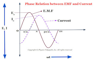
Now compare equation $(1)$ and equation $(2)$ which shows that an alternating circuit containing an inductor only, the current lags behind the emf by a phase angle of $\frac{\pi}{2}$ or $90^\circ$ (or the emf leads the current by a phase angle of $\frac{\pi}{2}$). The phase diagram between EMF and the current of an inductor is shown below-
Phase Relation between EMF and Current of an Inductor
The phasor diagram between the EMF and current of an inductor is also shown in the given figure below-
Phasor Diagram between EMF and Current of an Inductor

Electric field Intensity (Definition) and Electric field Intensity due to point charge

Definition of Electric Field Intensity:

The force acting on the per unit test charge in electric field is called the Electric field intensity. It is represented by $'E'$.

Let us consider that a test-charged particle of $q_{0}$ Coulomb is placed at a point in the electric field and a force $F$ acting on them so the electric field intensity at that point

$ \overrightarrow{E}=\frac{\overrightarrow{F}}{q_{0}}$

SI Unit:$\quad Newton/Coulomb$ $ (N/C)$ $\quad Kg-m^{2}/sec^{3} A$

Dimension: $\left [ML^{2}T^{-3}A^{-1} \right ]$

Physical Significance of Electric Field:

The force experienced by a charge is different at different points in space. So electric field intensity also varies from point to point. In general, Electric field intensity is not a single vector quantity but it is a set of infinite vector and each point in space have a unique electric field intensity. So electric field is an example of the vector field.

Electric Field Intensity due to a Point Charge:

Let us consider that an isolated point charge of $+q$ Coulomb is placed at a point $O$ in a medium whose dielectric constant is $K$. If a test charge particle of $q_{0}$ Coulomb is placed at a point $P$ in the electric field at a distance $r$ from point $O$. So the electric field intensity (magnitude form) at point $P$
Electric field intensity due to a point charge
$E=\frac{F}{q_{0}}\qquad (1)$

According to Coulomb's Law:

$F=\frac{1}{4\pi \varepsilon _{0}K}\frac{qq_{0}}{r^{2}}\qquad (2)$

From equation $(1)$ and equation $(2)$, we can write

$E=\frac{1}{4\pi \varepsilon _{0}K}\frac{q}{r^{2}} \qquad (3)$

For air or vacuum $K=1$, Then from equation $(3)$

$E=\frac{1}{4\pi \varepsilon _{0}}\frac{q}{r^{2}} \qquad (4)$

Where

$\frac{1}{4\pi \varepsilon _{0}}=9\times10^{9} N-m^{2}/C^{2}$

From equation $(4)$

$E=9\times 10^{9} \frac{q}{r^{2}}\qquad (5)$

In Vector Notation:

$\overrightarrow{E}=\frac{1}{4\pi \varepsilon _{0}K}\frac{q}{r^{2}}r\hat{}$

If a system containing $'n'$ point charge $q_{1},q_{2},q_{3},..........q_{n}$ then electric field intensity due to the system of charge particle will be equal to the vector sum of the intensities i.e.

$\overrightarrow{E}=\overrightarrow{E_{1}}+\overrightarrow{E_{2}}+\overrightarrow{E_{3}}+....+\overrightarrow{E_{n}}$

$\overrightarrow{E}=\frac{1}{4\pi \varepsilon _{0}K}\sum_{i=0}^{n}\frac{q_{i}}{r_{i}^{2}}r_{i}\hat{}$

Where $r_{i}$ is the distance from point $'P'$ to charge $q_{i}$.

Refraction of light and its Properties

Definition of Refraction of light→ When a light goes from one medium to another medium then light bends from the path. This bending of the light phenomenon is knowns as the refraction of light.

When light goes from a rarer medium to a denser medium, light bends toward the normal as shown in the figure below:
Propagation of light from rare medium to denser medium
Propagation of light from rarer medium to denser medium
When light goes from a denser medium to a rarer medium, the light goes away from normal as shown in the figure below.
Propagation of light from denser medium to rarer medium

Properties of refraction of light→

  1. The incident ray, normal ray, and refracted ray lie on the same point.
  2. According to Snell's law - The ratio of the sine of the incident angle to the sine of the refractive angle is always constant. This constant value is known as the refractive index of the medium.

$\frac{sin \: i}{sin \: r}=constant(_{1}n_{2}) $

$\frac{sin \: i}{sin \: r}= (_{1}n_{2})$

$\frac{sin \: i}{sin \:r}=\frac{n_{2}}{n_{1}}$

Where $_{1}n_{2}$ is the refractive index of medium $(2)$ with respect to medium $(1)$ .

Absolute refractive index→

The ratio of the speed of light in a vacuum to the speed of light in a medium is called the absolute refractive index of the medium.

$refractive\: index(n)=\frac{speed\: of\:light\: in\: vacuum(c)}{speed \:of \:light\: in\: medium(v)}$

$n=\frac{c}{v}$

Note

According to Snell's law -

$\frac{sin \: i}{sin \: r}=\frac{n_{2}}{n_{1}} \quad\quad (1)$

$\frac{sin \: i}{sin \: r}=\frac{\frac{c}{v_{1}}}{\frac{c}{v_{2}}} \quad\quad \left \{ \because n=\frac{c}{v} \right \}$

$\frac{sin i}{sin r}=\frac{v_{1}}{v_{2}} \qquad (2)$

When the light goes from one medium to another medium frequency of the light does not change but the wavelength of the light changes. So above given equation can be written as

$\frac{sin \: i}{sin \: r}=\frac{\nu \lambda_{1}}{\nu \lambda_{2}} \quad\quad \left \{ \because v=\nu \lambda \right \} $

$\displaystyle \frac{sin \: i}{sin \: r}=\frac{\lambda_{1}}{ \lambda_{2}} \qquad (3)$

From equation $(1)$ ,equation $(2)$, and equation $(3)$ we can write the equation

$\frac{sin \: i}{sin \: r}=\frac{n_{2}}{n_{1}} =\frac{v_{1}}{v_{2}}= \frac{\lambda_{1}}{ \lambda_{2}}$

Conditions for a light ray to pass undeviated on refraction of light→

A ray of light passes undeviated from medium $1$ to medium $2$ in either of the following two conditions:

  1. When the angle of incidence at the boundary of two media is zero $\angle i =0^{\circ} so \ \angle r= 0^{\circ}$.
  2. When the refractive index of the medium (2) and medium (1) is the same i.e. $i=r$.

Factors affecting the refractive index of the medium→

The refractive index of a medium depends on basically following three factors:

1. Nature of the medium (on the basis of speed of light)→ Less the speed of light in the medium as compared to that in the air more is the refractive index of the medium. $\left ( n=\frac{c}{v}\right)$

Speed of light in glass- $v_{glass} = 2\times 10^{6} ms^{-1}$

$\mu_{glass} = 1\cdot 5$

Speed of light in water- $v_{water} = 2\cdot25\times10^8ms^{-1}$

$\mu_{water} = 1\cdot33$

2. Physical conditions such as temperature→ With the increase in temperature, the speed of light in the medium, so the refractive index of the medium decreases.

3. The colour or wavelength of light→ The speed of light of all colours is the same in the air ( or vacuum), but in any other transparent medium, the speed of light is different for different colours. In a given medium the speed of red light is maximum and that of the violet light is least, therefore the refractive index of that medium is maximum for violet is and least for red light i.e. $\left ( \ n_{violet}> n_{red}\right )$. The wavelength of visible light increase from violet to red end, so the refractive index of a medium decreases with the increases in wavelength.

Alternating Current Circuit containing Resistance only (R-Circuit)

Alternating Current Circuit containing Resistance (R-Circuit): Let us consider, An alternating current circuit containing resistance $R$ only. This resistance $R$ is connected with an alternating EMF i.e electromotive force source i.e.
Alternating Current Circuit Containing Resistance only
$E=E_{\circ}sin\omega t\qquad(1)$

The potential difference across the circuit

$E=iR$

Then from equation $(1)$

$iR=E_{\circ}sin\omega t $

$i=\frac{E_{\circ}}{R}sin\omega t $

$i=i_{\circ}sin\omega t \qquad(2) $

Where $i_{\circ}$ is the peak value or amplitude of the current in the circuit which has value $i_{\circ}=\frac{E_{\circ}}{R}$.

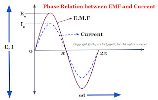
Now compare the equation $(1)$ and equation $(2)$ which shows that if a circuit is containing a resistor only then the current is always in phase with the applied EMF i.e electromotive force. The phase diagram between EMF and the current of resistance is shown below-
Phase relation between EMF and Current
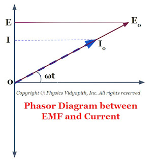
The phasor diagram between the EMF and current of resistance is also shown in the given figure below-
Phasor Diagram between EMF and Current

Derivation of Addition of Velocity in Special Relativity

Addition of Velocities:

Let us consider two frames $S$ and $S'$, frame $S'$ is moving with constant velocity $v$ relative to frame $S$ along the positive direction of the X-axis.

Let us express the velocity of the body in these frames. Suppose that body moves a distance $dx$ in time $dt$ in frame $S$ and through a distance $dx'$ in the time $dt'$ in the system $S'$ from point $P$ to $Q$. Then
Addition of velocity

$\frac{dx}{dt} = u\qquad \frac{dx'}{dt'}= u'\qquad (1)$

From Lorentz's inverse transformation

$x=\alpha\left ( x'+vt' \right )\qquad(2)$

$t=\alpha '\left ( t'+\frac{v\cdot x'}{c^{2}} \right )\qquad(3)$

Differentiate the equation $(2)$ and equation $(3)$ with respect to $t'$

$\frac{dx}{dt'}= \alpha \left ( \frac{dx'}{dt'}+v \right )\qquad(4)$

$\frac{dt}{dt'}= \alpha ' \left ({1}+\frac{v}{c^{2}} \cdot \frac{dx'}{dt'} \right )\quad (5)$

Now divide the equation $(4)$ by equation $(4)$. So

$\frac{\frac{dx}{dt'}}{\frac{dt}{dt'}} = \left ( \frac{\frac{dx'}{dt}+v}{1+\frac{v}{c^{2}}\cdot \frac{dx'}{dt'} } \right ) \qquad $

From Lorentz Transformation $\alpha =\alpha '$. So above equation can be written as:

$\frac{dx}{dt} = \frac{u' +v}{1+ \frac{u'v}{c^{2}}}$

From equation $(1)$. The above equation can be written as:

$u = \frac{u' +v}{1+ \frac{u'v}{c^{2}}} $

This equation represents the relativistic law of addition of velocities with respect to an observer at frame-$S$ whereas in classical mechanics it is simply $u = u'+v$. There is the following point observed from the addition of the velocities equation.
  1. When $u'$ and $v$ are the smaller as compare to $c$, then $\frac{v\cdot u'}{c^{2}}$ can be negligible so

    $u = u'+v$

    which is classical formula.

  2. When $u' = c$Then $u =\frac{c+v}{1+\frac{v}{c}}$ So,

    $u=c$

    Therefore a object moves with velocity of light $c$ with respect to other, then their relative velocity is always $c$.

  3. When $v=u'=c$Then $u =\frac{c+c}{1+\frac{c^{2}}{c^{2}}}=c$ So,

    $u=v$

    This shows that the addition of the velocity of light simply reproduces the velocity of light. It means that the velocity of light in a vacuum is the maximum achievable velocity in nature and no signal and any object can travel faster than the velocity of light in a vacuum.


Work done by a rotating electric dipole in uniform electric field

Derivation of Work done by a rotating electric dipole in uniform electric field :

Let us consider, An electric dipole AB, made up of two charges $+q$ and $-q$, is placed at a very small distance $2l$ in a uniform electric field $\overrightarrow{E}$. If dipole $AB$ rotates at angle $θ$ from its equilibrium position. If $A'$ and $B'$ are the new position of a dipole in the electric field. Then force on $+q$ charge particle due to electric field→

$ \overrightarrow{F_{+q}}=q\overrightarrow{E}\qquad (1)$

Then force on $-q$ charge particle due to electric field→

$ \overrightarrow{F_{-q}}=q\overrightarrow{E}\qquad(2)$
Work done by rotating an electric dipole in an external uniform electric field
Work done by rotating an electric dipole 
So work done by a force on $+q$ charge particle to bring from position $A$ to position $A'$→

$ \overrightarrow{W_{+q}}=\overrightarrow{F_{+q}}·\overrightarrow{AC}$

$ \overrightarrow{W_{+q}}=q\overrightarrow{E}· \overrightarrow{AC}\qquad(3)$

Similarly, work done by the force on $-q$ charge particle to bring from position $B$ to position $B'$→

$ \overrightarrow{W_{-q}}=\overrightarrow{F_{-q}}·\overrightarrow{BD}$

$ \overrightarrow{W_{-q}}=q\overrightarrow{E}· \overrightarrow{BD}\qquad (4)$

So the total work is done by the force on the dipole→

$ \overrightarrow{W}=\overrightarrow{W_{+q}}\:+\:\overrightarrow{W_{-q}}$

$\overrightarrow{W}=q\overrightarrow{E}·(\overrightarrow{AC}+\overrightarrow{BD})\qquad (5)$

From the figure, There is symmetry so

$ \overrightarrow{AC}=\overrightarrow{BD}$

So from equation $(5)$

$ \overrightarrow{W}=q\overrightarrow{E}·(2\overrightarrow{AC})$

$ \overrightarrow{W}=2q\overrightarrow{E}(\overrightarrow{AO}-\overrightarrow{CO})\qquad (6)$

From figure→

$ \left | \overrightarrow{AO} \right |=l$

$ \left | \overrightarrow{CO} \right |=l\:cos \theta$

Now substitute the values in equation (6). So equation (6) can be written as in magnitude form →

$ W=2qE(l-l\:cos\theta )$

$ W=2qEl(1-cos\theta )$

$ W=pE(1-cos\theta )$

The above expression shows that work is done on a rotating electric dipole in a uniform electric field.

Case (i):

If $\theta=0^{\circ}$, Then work done will be minimum

$W_{min}=0$

Case (ii):

If $\theta=90^{\circ}$, Then work done

$W=pE$

Case (iii):

If $\theta=180^{\circ}$, Then work done will be maximum

$W_{max}=2pE$

Electric field Intensity due a uniformly charged Spherical Shell

Electric field intensity at a different point in the field due to the uniformly charged spherical shell:

Let us consider, a spherical shell of radius $R$ in which $+q$ charge is distributed uniformly on the surface of the sphere. Now find the electric field intensity at different points due to the spherical shell. These different points are:

1.) Electric field intensity at an external point of the spherical shell
2.) Electric field intensity on the surface of the spherical shell
3.) Electric field intensity at an internal point of the spherical shell

1. Electric field intensity at an external point of the spherical shell:

If point $O$ is the center of the spherical shell, The electric field at the outside of the spherical shell can be determined by the following steps →

1.) First, take the point $P$ outside the sphere
2.) Draw a spherical surface of radius r which passes through point $P$.This hypothetical surface is known as the Gaussian surface.
3) Now take a small area $\overrightarrow {dA} $ around point $P$ on the Gaussian surface to find the electric flux passing through it.
4.) Now find the direction between the electric field vector and small area vector.

Due to uniform charge distribution, the electric field intensity will be the same at every point on the Gaussian surface. So from the figure,
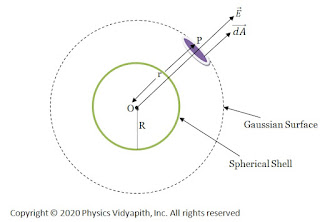
Electric field intensity due to the uniformly charged spherical shell
Electric field intensity due to the uniformly charged
The direction of electric field intensity on the Gaussian surface is radially outward which is in the direction of the area vector of the Gaussian surface. i.e. ($\theta=0^{\circ}$).Here $\overrightarrow {dA}$ is small area around point $P$ so the small electric flux $d\phi_{E}$ will pass through this small area $\overrightarrow {dA}$. so this flux can be found by applying the Gauss's law in question given below:

$ d\phi_{E}= \overrightarrow {E}\cdot \overrightarrow{dA}$

$ d\phi_{E}= E\:dA\: cos 0^{\circ} \qquad \left \{\because \theta=0^{\circ} \right \}$

$ d\phi_{E}= E\:dA \qquad (1) \quad \left\{\because cos0=1 \right \}$

The electric flux passing through the entire Gaussian surface, So integrate the equation $(1)$ →

$ \phi_{E}=\oint E\:dA\qquad(2)$

According to Gauss's law:

$ \phi_{E}=\frac{q}{\epsilon_{0}}\qquad (3)$

From equation (1) and equation (2), we can write as

$ \frac{q}{\epsilon_{0}}=\oint E\:dA$

$ \frac{q}{\epsilon_{0}}= E\oint dA$

The area of entire Gaussian spherical is $\oint {dA}=4\pi r^{2}$. Now substitute this value in above equation. So above equation can be written as:

$ \frac{q}{\epsilon_{0}}= E(4\pi r^{2})$

$ E=\frac{1}{4\pi \epsilon_{0}}\frac{q}{r^{2}}$

From the above equation, we can conclude that the behavior of the electric field at the external point due to the uniformly charged spherical shell is the same as, like the entire charge is placed at the center, point charge

If the surface charge density is $\sigma$, Then total charge $q$ on the surface of a spherical shell is →

$ q=4\pi R^{2}\: \sigma$

Substitute this value of charge $q$ in above equation, so we can write the equation as:

$ E=\frac{1}{4\pi \epsilon_{0}}\frac{4\pi R^{2}\: \sigma}{r^{2}}$

$ E=\frac{\sigma}{\epsilon_{0}}\frac{R^{2}}{r^{2}}$

This equation describes the electric field intensity at the external point of the spherical shell.

2. Electric field intensity on the surface of the spherical shell:

If point $P$ is placed on the surface of the spherical shell i.e ($r=R$). so electric field intensity on the surface of the spherical shell can be found by putting $r=R$ in the formula of the electric field intensity at the external point of the spherical shell:

$ E=\frac{1}{4\pi \epsilon_{0}}\frac{q}{R^{2}}$

$ E=\frac{\sigma}{\epsilon_{0}}$

3. Electric field intensity at an internal point of the spherical shell:

If point $P$ is placed inside the spherical shell then the electric field intensity will be zero at that point because the charge is distributed uniformly on the surface of the solid sphere so there will not be any charge on the Gaussian surface and electric flux will be zero inside the solid sphere. i.e.

$ \phi_{E}=\oint E\:dA$

$ 0=E\oint dA \qquad \left \{ \because \phi_{E}=0 \right \}$

$ E=0$

Electric field intensity distribution with distance for Spherical Shell:

Electric field intensity distribution with distance shows that the electric field is maximum on the surface of the sphere and zero inside the sphere. Electric field intensity distribution outside the sphere reduces with the distance according to $E=\frac{1}{r^{2}}$.
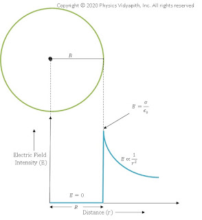
Electric field intensity distribution with distance for Spherical Shell
Electric field intensity distribution with distance

Popular Posts

Study-Material


  • Classical world and Quantum world

  • Inadequacy of classical mechanics

  • Drawbacks of Old Quantum Theory

  • Bohr's Quantization Condition

  • Energy distribution spectrum of black body radiation

  • Energy distribution laws of black body radiation

  • The Compton Effect | Experiment Setup | Theory | Theoretical Expression | Limitation | Recoil Electron

  • Davisson and Germer's Experiment and Verification of the de-Broglie Relation

  • Significance of Compton's Effect

  • Assumptions of Planck’s Radiation Law

  • Derivation of Planck's Radiation Law

  • de-Broglie Concept of Matter wave

  • Definition and derivation of the phase velocity and group velocity of wave

  • Relation between group velocity and phase velocity ($V_{g}=V_{p}-\lambda \frac{dV_{p}}{d\lambda }$)

  • Group velocity is equal to particle velocity($V_{g}=v$)

  • Product of phase velocity and group velocity is equal to square of speed of light ($V_{p}.V_{g}=c^{2}$)

  • Heisenberg uncertainty principle

  • Generation of wave function for a free particle

  • Physical interpretation of the wave function

  • Derivation of time dependent Schrodinger wave equation

  • Derivation of time independent Schrodinger wave equation

  • Eigen Function, Eigen Values and Eigen Vectors

  • Postulate of wave mechanics or Quantum Mechanics

  • Quantum Mechanical Operators

  • Normalized and Orthogonal wave function

  • Particle in one dimensional box (Infinite Potential Well)

  • Minimum Energy Or Zero Point Energy of a Particle in an one dimensional potential box or Infinite Well

  • Normalization of the wave function of a particle in one dimension box or infinite potential well

  • Orthogonality of the wave functions of a particle in one dimension box or infinite potential well

  • Eigen value of the momentum of a particle in one dimension box or infinite potential well

  • Schrodinger's equation for the complex conjugate waves function

  • Probability Current Density for a free particle in Quantum Mechanics

  • Ehrenfest's Theorem and Derivation

  • Momentum wave function for a free particle

  • Wave function of a particle in free state

  • One dimensional Step Potential Barrier for a Particle


  • Blog Archive